Waddlemarsh
Posted

Full Member
Somewhere SW of London. Somewhen before today
A double slip that I made nearly thirty years ago has "switches" between the rails, they're simply made with 9 thou guitar wire about half an inch long, when the point blades move the guitar wire connected to the tie bars touches a pin which is wired to the frogs causing contact.There's two to each tie bar depending on the point direction, one is alway in contact and the other open, when the points are changed, the open one closes and the closed on opens. :)
 Last edit: by Phil.c
Phil

Posted

Site staff
back soon
Ron
NCE DCC ; 00 scale UK outline.
NCE DCC ; 00 scale UK outline.
Posted
Site staff
I have marked up your drawing deleting some insulators and feeds, added feed 6, altered RHS 4 to 7 and a 4 to 5
it will mean some additional switching.
my drawing removed as requested. Feb 11
Ron
NCE DCC ; 00 scale UK outline.
NCE DCC ; 00 scale UK outline.
Posted
Site staff
Ron
NCE DCC ; 00 scale UK outline.
NCE DCC ; 00 scale UK outline.
Posted

Full Member
The electrofrog double-slip which has been the cause of most of the electrical problems - either directly or indirectly - has been replaced with an insulfrog version.
I can paint the brown plastic frogs a better colour than they are. So far nothing stalls on them. And - after a minor hiccup which was expected on a trial and error basis - everything works. I fitted metal joiners to all ends but found that one arm needed IRJs to avoid shorting. With those fitted all the problems on the main part of the layout are now resolved.
Now to move on to the custom-built crossover which has its own wiring plan. And which now has Peco PL-15 accessory switches to replace the double-stacked frog switches suggested by the plan.
I can also now move on - once the disturbed ballasting has been made good - with other scenic and detailing work since all the remaining wiring (points and signals) is beneath the boards and will not require surface disturbance.
Posted
Full Member
Posted
Full Member
Stuff moving. Crudely filmed on the iPhone with one hand while the other managed three controllers. But it shows that stuff moves as it should over this half of the layout at last. I still need to fit a few switches to have it exactly as I want but it's come a long way in the last few days.
Now to work on the other end where another double slip lurks awaiting my attention …..
Posted
Full Member
Looks good, I like the two class 33’s. I need to get me one of them!
Posted

Full Member
Good standard of weathering too - I wonder who did that ………………….

'Petermac
Posted
Full Member
Posted
Site staff
See, if you hadn't moved back to the UK, you had plenty of room Down Under on Penhayle BayAs I am no longer able to run 12-coach main-line trains I have too much rolling stock now stored away and am unlikely to need all of it in the future.
 :pedal
Ron
NCE DCC ; 00 scale UK outline.
NCE DCC ; 00 scale UK outline.
Posted
Full Member
:cheers
Jeff Lynn,
Amateur layabout, Professional Lurker, Thread hijacker extraordinaire
Amateur layabout, Professional Lurker, Thread hijacker extraordinaire
Posted
Full Member
So true. But if I hadn't moved back to the UK I would be missing a very important person who - subject to final examination - is about to become a Doctor of Environmental History and has just scored herself a Cambridge University invitation to lecture and lead workshops later this year.[user=1753]Gwiwer[/user] wrote:See, if you hadn't moved back to the UK, you had plenty of room Down Under on Penhayle BayAs I am no longer able to run 12-coach main-line trains I have too much rolling stock now stored away and am unlikely to need all of it in the future.
We still own the house in Australia though have no plans to return for the foreseeable future. And I still own enough of the buildings and structures that if ever there was to be space I could reasonably easily re-create at least a part of Penhayle Bay.
In the meantime I shall Waddle on.
Posted
Full Member
Both turnouts are dead. The straight route curiously receives very low power. There is no short indicated nor do locos behave as though it is shorting - they simply slow down but continue.
The multimeter shows there is 13v when the controller is at full power, and this is available through both left and right-hand rails and all the way along the sidings provided the other side is connected to a rail on the toe-side of the little plastic lug in the blades. For the middle road the meter shows a current of 3.5v all the way through.
Stumped? I certainly am.
Posted
Site staff
Ron
NCE DCC ; 00 scale UK outline.
NCE DCC ; 00 scale UK outline.
Posted
Full Member
Jeff Lynn,
Amateur layabout, Professional Lurker, Thread hijacker extraordinaire
Amateur layabout, Professional Lurker, Thread hijacker extraordinaire
Posted
Full Member
In my very confined space I have built the main yard on top of a bookshelf across my office desk. I cannot therefore drill into it to run wiring beneath although, as it is an off-scene yard, I could run surface wiring.
I am also thinking about the number of switches I am now going to need. Again there is a limit of space for the control area which must accommodate point levers, a few signal levers and a number of isolation switches. The latter is all part and parcel of the electrofrog "experience" and if I was building this project from scratch as opposed to re-using previously-built and track-laid boards I might well have used insulfrogs from the outset.
I'll have a think on the way forward.
Posted
Full Member
Jeff Lynn,
Amateur layabout, Professional Lurker, Thread hijacker extraordinaire
Amateur layabout, Professional Lurker, Thread hijacker extraordinaire
Posted
Full Member
Meanwhile I can make progress on the scenic side of things. Working more or less from the back to the front the first feature will be the creation of Waddlemarsh Halt.
This will just (only just!!) accommodate a standard SR 4-car train although 2-car would be more common. 2-Bil and 2-EPB types will be the norm with others turning up or running through from time to time. The sidings allow for up to 6-car trains.
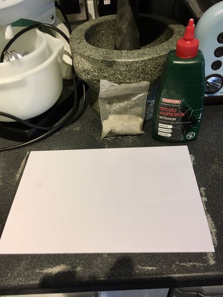
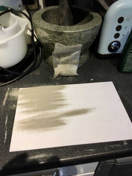
Not finding anything readily available to represent SR “Exmouth Junction†concrete slab platforms I have invested in some 3mm foam-board sections. These have been coated in neat PVA brushed evenly and coated with a fine sand which was first used for the unpaved platform areas in the final version of Treheligan station on my previous layout.
Also not having any work bench means the task was performed in the kitchen while no-one else was looking.
One brush is used for spreading the adhesive. A second brush is used for sweeping up the excess sand.
Bald spots can be rectified later using spray-on PVA. The sheets can then be cut to size and slab joins scored in them. I am hoping to create the uprights by similar means.


Last edit: by Gwiwer
Posted
Full Member
What ever the cause the point is irretrievably b*****ed and will indeed be replaced with an insulfrog version. The difference between asymmetric and symmetric, also the difference between Code 75 and Code 100, are not critical. I can drop in a code converter rail at the toe end of the new point and the sidings it feeds are already code 100 rail.
In the interim and until the new point arrives I have dropped in a spare point which I have to hand and which serves four of the five sidings. There are no electrical issues and it behaves exactly as I expect an electrofrog point feeding dead-end sidings would.
Which makes me wonder if there was a bigger problem with the now-deceased three-way in the first place. I may never know
1 guest and 0 members have just viewed this.