Upper Hembury GWR Branch Line
Posted

Full Member
Updated plans and now moving ahead
[user=1120]peterm[/user] wrote:Thx Peter,….
I had a large layout under our previous house and built a cdu hefty enough to throw eight points in one go. Needless to say I had to put resistors in for single point motors.
Tell me more about the resistors you used. I'd thought of that route but was worried the high instantaneous current would be an issue.
What resistance (ohms) and current rating if you an remember. That would be of interest!
 Last edit: by Colin W

Posted

Site staff
Ron
NCE DCC ; 00 scale UK outline.
NCE DCC ; 00 scale UK outline.
Posted
Full Member
Cheers Pete.
Posted
Full Member
Posted
Full Member
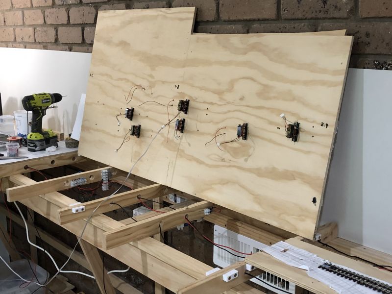
I've temporarily joined two separate panels as some of the turnouts and track overlap the central cut. In this design all solenoid feeds are three wire lead so I settled on JST 3-pin plugs and sockets. They work very well, are easy to assemble and make testing and changes very easy work.
As ever, precise alignment of the turnout tie bar with the motor pin is the most tricky but even this was made easier with the hole alignment tool referred to earlier.
Last edit: by Colin W
Posted
Full Member
Recently, I posted this elsewhere on YMRC but was not killed by a tsunami of answers, so here goes with try #2.
Having cork higher on the main (1.5mm) than in sidings (none) is what I finally chose for Upper Hembury. So it's the same 1.5mm transition as favoured by at least one respondent to my poll.
Now I'm into laying track, how do I best "fade" from the 1.5mm elevation down?
I was thinking perhaps a progressively thinning layer of card but that's quite some work as I'll have 6 lines in total.
Also over what distance to make the transition?
All suggestions welcomed please!
If all else fails, I'll put it down all using the same underlay, I have appropriate trap turnouts in the design.
Colin
Last edit: by Colin W
Posted

Full Member
Cork simply refuses to accept sanding (with domestic sanders at least) and 1.5mm only requires a small gradient ………
My thoughts would be cardboard packing at mid point then, when the time comes, infill the voids with ballast.
As for the length of the grade - as ever, as long as possible ………..
'Petermac
Posted
Full Member
Terry
Posted
Full Member
Others' solutions remain of interest as I've a little time yet until I get to sidings. Next up is testing all the main track which I've laid.
Posted
Full Member
For some reason which I can't fathom, I have always wrongly assumed that the ballast should be 1ft (or 4mm in 4mm scale) deep.
Terry
Last edit: by col.stephens
Posted
Full Member
Thanks Terry,Just a thought Colin on the depth of the ballast. According to my copy of 'Requirements For Passenger Lines And Recommendations For Goods Lines' published by HMSO 1950, on important lines there should be not less than 6 inches of ballast below sleeper beds. So, strictly speaking, your cork or whatever should be at least 2mm thick if you are modelling in 4mm scale.
For some reason which I can't fathom, I have always wrongly assumed that the ballast should be 1ft (or 4mm in 4mm scale) deep.
Terry
fortunately plenty of wriggle room for me in the above, viz.
1950 - ( I'm much earlier)
important line - hardly
very little of the passenger line tracks will be visible from the viewing side, obscured by station, signal box, sidings etc
and finally in the setting I can hopefully give the impression of greater depth than my cork permits
Last edit: by Colin W
Posted
Full Member
Of course, half a millimetre difference in the thickness of the cork trackbed is going to make no difference at all. And anyway, it's your layout and Rule 1 applies!
Terry
Posted
Full Member
Firstly; how to moderate the action of an overly forceful solenoid in three easy steps.
1) regulate the voltage; in my case I dialed down to the voltage which worked fine over my longest line.
Ceramic Resistors inserted in line have been used by others when there are significantly different needs at different solenoids in a set up.
2) add a PL-13 beneath (Its normal purpose is to enable frog power switching but here purely acts as a resistance brake preventing blade recoil)
thanks to helpful input I've taken to pulling the PL-13 apart and lubricating the contact surfaces with graphite powder to give me consistent operation
3) add a shock absorber inside the PL-9 mounting Plate
This is shown in the photo below.
It is a strip of the second toughest material (after Kryptonite) known to man, viz, an old credit card!
Cut into a strip with a narrow slot about 2.5mm -3mm long in the centre. This to restrict the solenoid wire travel too far to each side.
Shock absorbance comes from a pea sized blob of Black tack at each side under the plastic card. The strip absorbs the shock of excess power from the solenoid remarkably well and quickly self- centres for continuing effective action.

Posted
Full Member
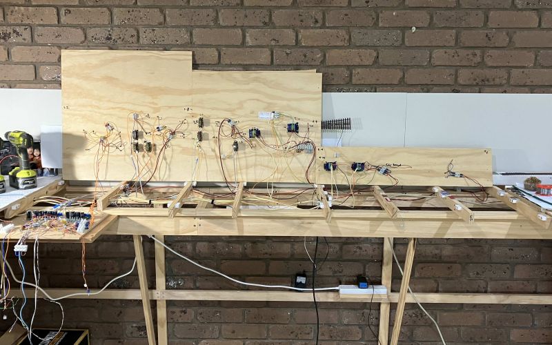
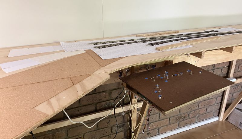
Droppers for all components and associated track are now in place, and not trusting that some gremlin won't pop up, I've used choc blocks to consolidate 2 or 3 sets of leads so that any necessary raising of the top boards will only involve a few main connections. Beginner's caution, no hard soldering here!
This shows how busy / central these 1200mm of board are to the whole, seven solenoids and 1 Cobalt (half the Single Slip). The benefits of consolidating the droppers are clearly visible WRT tidiness. Leads are not labelled but the sources are, that might be something to come back to do later.
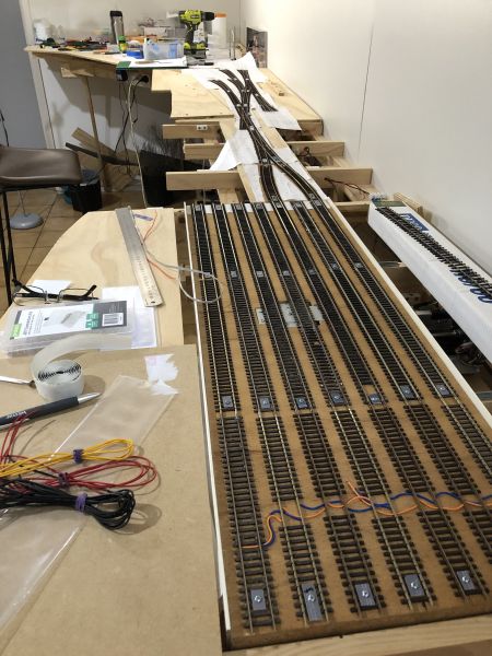
The topside view is little changed except that all the relevant track is here together.
Posted

Full Member
Loving the traverser - 7 tracks for a good range of trains.
Barry
Shed dweller, Softie Southerner and Meglomaniac
Posted
Full Member
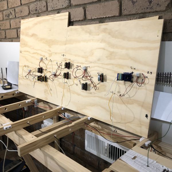
In this post the original base-plate to the Control panel is shown. More of this later, for now suffice to say that my 4 Cobalts have been installed on the most critical turnouts, Slip *2 + one on the approach road to the traverser and another on the Goods Yard / Runaround main entrance. All work very well.
What you see is mostly recycled wiring.
The cobalts require three lines, I chose 15V DC +/-( to match my Solenoid feed) and a line bisecting this voltage, designated for feedback / LEDs on the Control panel. There is a minor point to note here; DCC Concepts helpful guide shows you how can insert opposed LEDs directly in the DC feed to provide direction indication back at the switch. This is true and would avoid the need for a third line; there is a BIG "however" lurking in this for the unaware!
The Cobalt Omega Classic has a maximum operating current of 20mA, this (I believe) regulating the flow thru the LEDs. I powered up the Cobalt and recoiled from the "Chernobyl" like flash of light surging from my indicator LED. Outshining my other tailored LED indicators like a Supernova over a Red Dwarf, I needed plan B. Here the feedback line is useful, unlike the power supply lines, this can have a resistor in line so popping in a 1KOhm my paired LEDs shone at the desired level.
For the connections I needed 3 line cable and here some recovered 4 stand Comms. cable, 16m of it which I'd carefully kept for that rainy day came handy. You can see the bundled cream cables that keep wiring very tidy. A combination of alternatively using the yellow and green as the feedback line and choice of 4 pin JST connector endings gave me unique wiring connections for each Cobalt back to Control.
Most of the other short dropper and connection leads were recovered from my final desktop PC. The various PS feeds there are a productive source of suitable lengths in Red, Black, Yellow and Orange cable of good weight.
A test run has not yet been tried as other matters drew me away, again. The Control Panel work will follow soon.
Posted
Full Member
The Control panel gave me some headaches, mainly because my mental image of how it would go together was somewhat deficient! There is a lot going on under the hood / bonnet and to cut a long story short a major rethink or two of the plan was needed to get it all together in a form that is accessible. The photo shows it in its current state but I suspect I'll be rebuilding it at some point down the track.
Other progress can also be seen here. Cork underlay has been put down for all the station lines and the runaround while the four lines exiting into the Goods area have card ramps to bring them down 1.5mm to baseboard level.
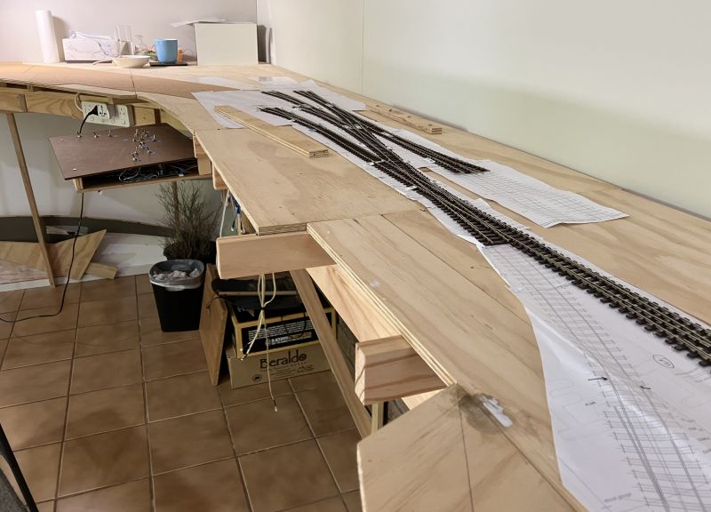
Finally, the track plan has been partially relaid, now on top of the cork, the earlier version having been too long in service as a workbench top / toolbox, drinks coaster and dumping ground etc. to its general detriment.

The station building is temporary, a hand me down from Westown-Heathfield and while the setting sits at the edge presently, the plan is to have a secondary board coming forward a short way. This will need to be removable to allow for access to the rear corner. The same will apply in front of the controls panel which is shown here pushed back, it slides out for use
Posted
Full Member
Barry
Shed dweller, Softie Southerner and Meglomaniac
Posted
Full Member
The first video goes onto the traverser and then returns via the other access road.
[yt]8eXzqwseLOU[/yt]
[yt]lgtFtVRFaVo[/yt]
Posted
Full Member
Cheers Pete.
1 guest and 0 members have just viewed this.