Upper Hembury GWR Branch Line
Posted

Site staff
Updated plans and now moving ahead
Spider Driver - superb !!!
Ron
NCE DCC ; 00 scale UK outline.
NCE DCC ; 00 scale UK outline.

Posted

Full Member
'Petermac
Posted

Full Member
At 6'4'', Bill is a tall chap, then again, when horizontal he is rather long and people often used to trip over him! . . . and so a nickname was born :)
Posted
Full Member
Cheers Pete.
Posted

Site staff
Wasnie me, a big boy did it and ran away
"Why did you volunteer ? I didn't Sir, the other three stepped backwards"
"Why did you volunteer ? I didn't Sir, the other three stepped backwards"
Posted
Full Member

'Petermac
Posted

Full Member
When all the grandkids were smaller it was standard amusement for them. While not all as good as Spider Driver, there are many great ones to enjoy. The kids always loved the aerial chases (HT to Star Wars I think) when hunted / hunter zoom at terrifying speed through low level (real) vegetation or buildings. The techniques where they marry real live footage with animation are superb.
In the spirit of Christmas, please enjoy these favourites of ours, there are many more to be found in the same place.
Down The Chimney
The Grocery Store Incident
Happy Christmas everyone. U-H has been put on hold for the coming period, W-H is back in situ for some holiday ops before work recommences on the new build in the new year.
 Last edit: by Colin W
Posted

Full Member
Posted
Full Member
As I was very happy with the service given by my PECO Solenoids driven by a CDU on Westown, I decided on sticking with the known, even though it has opened up some unexpected obstacles. More of those later, as in this post I wanted to share a tip I'd been given by others over on RMWeb # about making installation under the layout easier. A clever template which gives you correct alignment of the mounting screw holes on kit built turnouts.

The first pic shows the idea, the blades are centred by inserting suitable spacers, here 0.75mm PS strip as the blade gap is a modest and impressive 2mm at the tie rod. The template is designed with a pin to pass through the tie bar centre hole and sit perpendicular to the track.
Two pilot holes mark the points for the mounting holes. The next pic has these moved further out and a squaring plate glued to the template
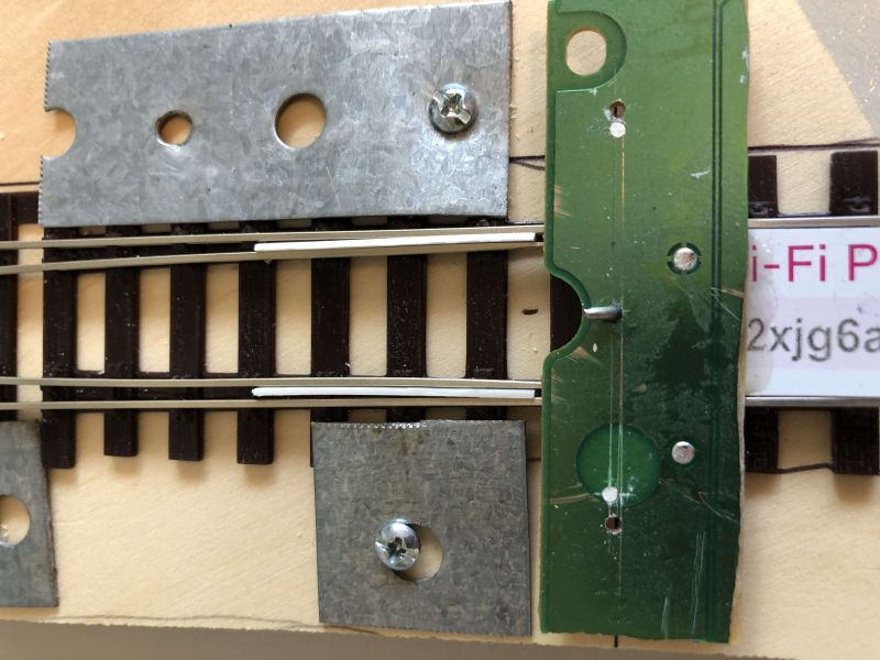
I'd previously used outside supports but these didn't work as well keeping it square. The Mark 2 works superbly, install was dead square first time with the motor pin sitting up vertical.
The underside of the template (the Mark 1 version) will give you the rest of the story. As you can see, an old piece of PCB was cleaned up as the core of the device.
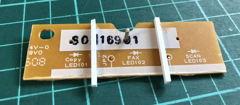
# originally from Michael Edge via St Enodoc
Posted
Full Member
A story best told by the photos
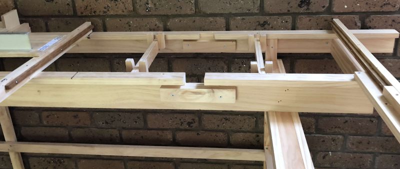

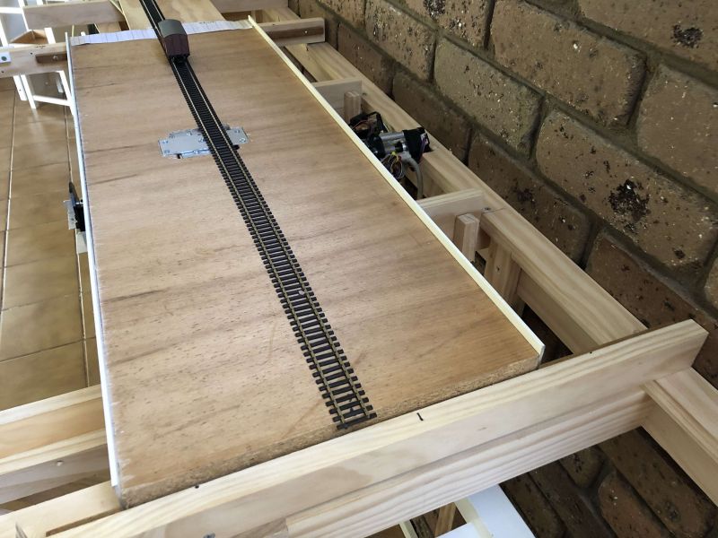
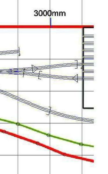
As the plan shows there are two merging exit lines, designed to cut down the required travel of the traverser. Here we need just 5 stopping positions and hence a maximum move of 4 to access any of the 7 lines.
Details of the mechanism to follow
Last edit: by Colin W
Posted
Full Member
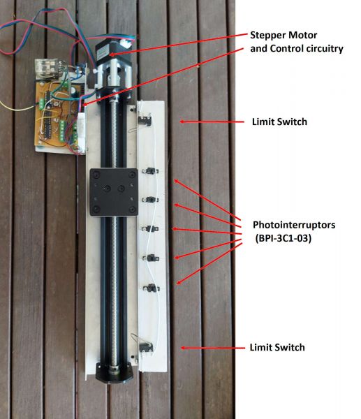
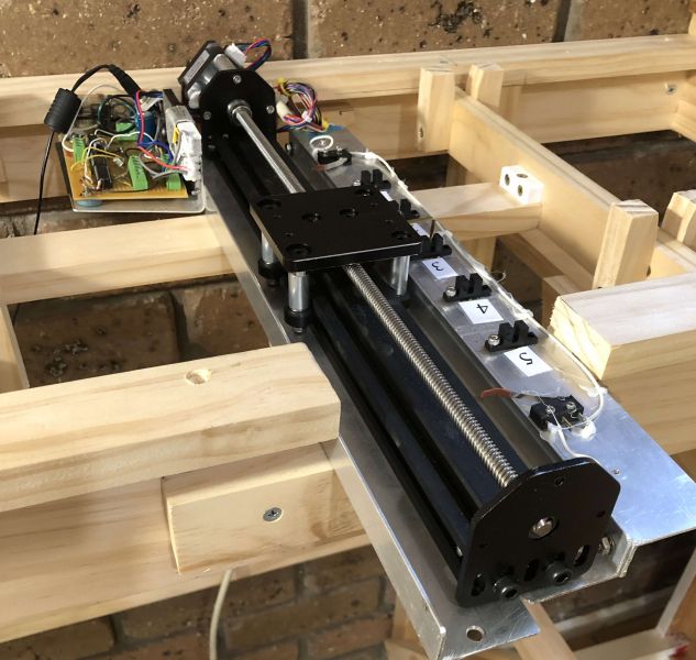
The Technical stuff #……
The traverser is moved by a screw driven stepper motor. The motor could be positioned by sending a fixed number of pulses to it, which is best implemented with a microprocessor. Instead, we have chosen simpler, readily available circuitry with no need for programming. The motor is driven until it reaches a position where the carriage blocks the light from a selected photo-interrupter. The photo-interrupter (BPI-3C1-03) is compatible with any that use a photo-transistor output. At that point the motor stops with no overrun, measured accuracy is within 1 motor step which equals <= 0.3mm lateral position. This is perfectly adequate for purpose.
The circuitry accomplishes this as follows;
The motor is driven by a UDN2998W dual H-bridge designed to drive bipolar stepper motors, which require the coil currents to be reversed in the correct phase. If + and – can be used to designate the direction of current flow, the first coil is driven ++–, while the second is -++-.The motor can be reversed by swapping the connections to either of the motor coils and is done by a Relay. The motor will run from 5V, however the UDN2998W will not, so the circuit is designed to run from 12V and 10 Ohm resistors are fitted to limit motor current.
# The details are all totally beyond my ken but if anyone is really interested I can check with the designer for his OK to share.
Once everything is installed, fine tuning of the Traverser plate is done by a simple adjustment to the locking plate which joins the plate to the moving section of the motor drive. With this design, screws could be conveniently positioned between the track lines, should the tray ever need removing for maintenance.
Last edit: by Colin W
Posted
Full Member
Cheers Pete.
Posted
Full Member
Inspired by Barry's fine efforts, I thought a short operation video of my traverser in action was overdue.
"Waltzing" to music which inspired Mr Pither on his Cycling Tour of Devon and N Cornwall #. Enjoy
[yt]_AOevFHHggI[/yt]
# Ep.34 of Monty Python - one of only two full half hour episodes and one of my favourites. Michael Palin at his annoyingly inoffensive best.
Last edit: by Colin W
Posted
Full Member
'Petermac
Posted

Full Member
The traverser looks fantastic and such an elegant solution to moving it from track to track. I am surprised its not been used more.
I have checked back through the thread but I can spot where you describe how the tracks are powered. Are the 7 traverser tracks powered with individually switches?
Best wishes
Posted
Full Member
Thanks Peter. There are three controls.That's brilliant Colin. Does it come back again….. :hmm
- Forward / Reverse
- A Lane selection rotary switch for the 5 positions
- An over-ride reset switch.
1) select Fwd, 2) turn the dial as required
immediately, the motor is set up to run until photosensor #5 is interrupted, not before.
Should you have "Reverse" selected by mistake, the traverser will happy ramble along, much as Reginald Pither does on his bike through Devon #, oblivious to the misdirection since there is no #5 ahead.
However unlike Reg, there is an end stop beyond both end photosensors which stops the motor so disaster in the form of burn out is avoided.
To recover, chose the correct direction and then hit reset and the movement to #5 will be completed. It's an error you make a few times before autopilot cuts in and then you always check the direction option first!
# so appropriate given Upper Hembry's location and the nature of the traverser motion.
Posted

Full Member

I shall be making a traverser one day (I would say soon, but I know it won't be) and it will be nothing as advanced as yours. A great job.
Michael
Posted
Full Member
Thank you John,Hi Colin
The traverser looks fantastic and such an elegant solution to moving it from track to track. I am surprised its not been used more.
I have checked back through the thread but I can spot where you describe how the tracks are powered. Are the 7 traverser tracks powered with individually switches?
Best wishes
The design which Graham came up with is very interesting. He has spent a very long time finding practical solutions to electronic and mechanical "challenges". These often arising when replacement of highly expensive lab kit was the only alternative, often not possible. He proudly tells of a 1970 vintage NMR# machine he maintained and we used in our postgrad days which was still working well some 45+years later.
I left the choice of design totally in his hands. It was only later I looked for mechanised traversers over in "the other place" that I found how little success people had had with using stepper motors. This AFAIK because they went the programming route to control which would be fine if you can get it right but clearly is not easy. It was why Graham specifically chose his route instead. He is planning to submit his design to an electronics magazine so I cannot supply more info.
Regarding powering the moving tray, here DCC comes truly into its element. No need for copper-clad, touching contacts etc.. All that will be needed is a short length of coiled 2 strand cable (e.g an electric razor power lead) extending the main power bus over to the tray. Wires from the bus to each track. I already power my removable goods extension over on Westown-Heathfield the same way.
# these days NMR is more familiar in a medical context as MRI. We used to use NMR to look at strange new chemicals we'd made to try and work out their structures, but that was a lifetime ago
Posted
Full Member
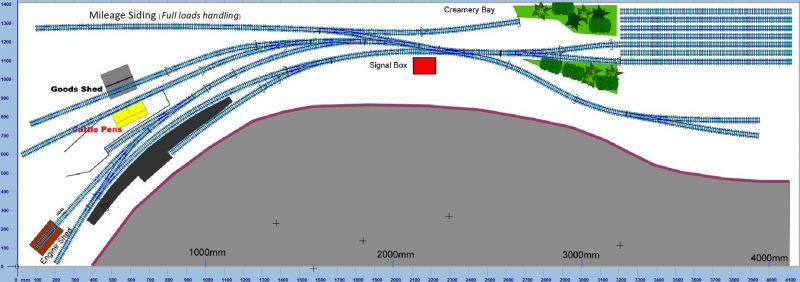
One last time for YT around the planning "loop".
With hindsight, it's a good job I went back and sought wider opinions # on my BLT design because I'd not understood some key issues regarding operations. As a result my sidings have been thinned out and lengthened, they are now very close to typical prototypical settings.
The key points in summary:
1) shunting was by default "off the main"
2) There was a very long mileage Siding where large loads were managed; smaller lots going thru the Goods Shed
I'd used Wallingford as my reference where the "free length" siding metrics are as follows:
Goods Shed line (100m,1320mm at scale);
Cattle Dock Siding (73m,960mm at scale)
Mileage siding (168m,2210mm at scale)
My revised plan shows what (with help) I've achieved which is something reasonably close to the Prototype.
# https://www.rmweb.co.uk/community/index.php?/topic/170320-upper-hembury-designing-a-gwr-branch-line-in-east-devon/
Last edit: by Colin W
Posted
Full Member
'Petermac
1 guest and 0 members have just viewed this.