Tinkers End
Posted

Full Member
East Coast Main Line - in the sun
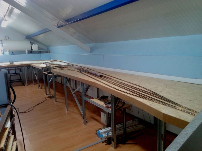
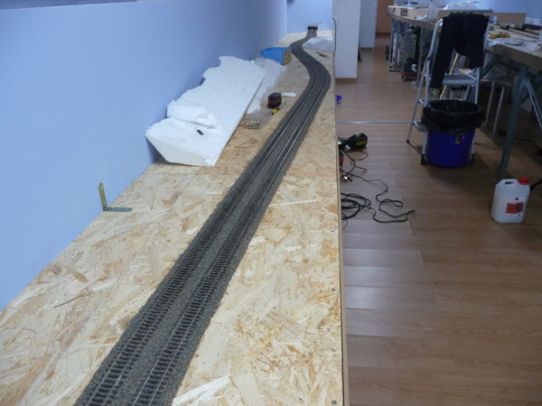
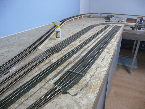
Well that's another month gone by. Where does all the time go. Milestone day today as I have finished laying all the track with the exception of the turntable area (which will be a long time coming given the cost of the turntable). So here as some pics.1. Northern end with one of the two main stations (Newtham). A Little over half way down is a lowered section to allow for a river. There are also links climbing to the branch line with Tinkers End station in the far right hand corner under the water tank.
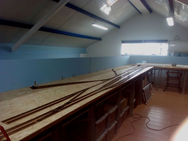
2. Centre section 1 which will be the main goods area with factories, quarry and closest too, the turntable and steam shed.
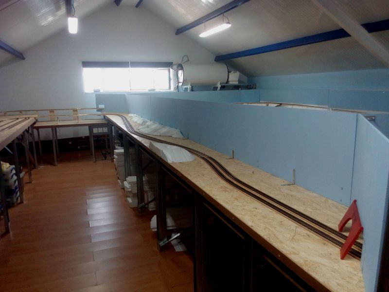
3. Centre section 2 will simply be some small hills, trees and countryside. At the far end you will see another lowered section for another river crossing.
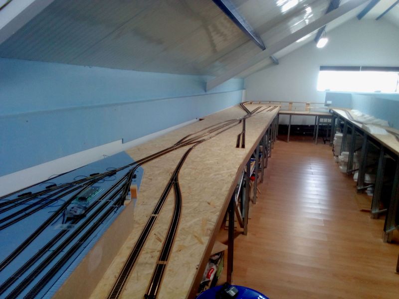
4. Southern end with the other main station (Granark). The branch line also comes back in at this point. There is also another small station bottom centre (Soar Point) just to add some extra running options. There is just a single line exiting off shot in to the southern fiddle yard.
Well that's about it for now. All the track has droppers soldered to it but these all need connecting underneath the baseboards before I can actually run trains all the way round. Still hopefull for Christmas but there is an awfull lot of soldering to be done.
Hope this is of interest.
 Last edit: by DaveH_Murcia

Posted

Full Member
Its too late for me but I do wish I had adopted your approach of laying all the track ( and I assume running trains? ) before attempting any scenery……far more practical than my modular approach.
A minor point and hardly an issue with the size of your layout…….but have you given any thought to where you will locate your TC profiling track? You need three level blocks, no intervening turnouts or curves. The start and finish blocks should be 2-3 feet long and the centre profiling block 6’ long. The set up should be easily accessible and ideally non scenic so you can have permanent distance markers for the brake compensation tests. You may know this already in which case my apologies
Best wishes
John
Posted
Full Member
Last edit: by DaveH_Murcia
Posted
Full Member
The start and end blocks need to be able to accommodate not just the longest loco/train but also have enough space for them to reach whatever speed is being tested/profiled.
I have 2’ start and end blocks ….the longest loco is 11â€. Its a good job that I have padded the ends with foam because the locos drive quite hard into the ends with the last 6 speed steps!
Regards
Posted
Full Member
Really looking forward to watching this progress
Posted
Full Member
Other than that, the main thrust has been on track detection cables. The left section is now about 50% complete although no points wired yet. The centre section already had all the lower fiddle yard done and tested so only a small amount more done. The right section is about 90% complete, it would have been 100% but someone got his cables crossed and wired across track detection sections. Just found it so a bit of rework to do tomorrow. Also fitted the first four of the DCC Concepts points in the scenic area in this section.
And finally - bought the full Traincontroller Gold licence so I can test things as I go along. Profiled my first loco (Deltic Pinza) which seemed to go OK although it does take an awfll long time to slow down. Once I get a couple more motors installed for one of the stations I should be able to start adding brake and stop markers and see how that all works out.
Oh, I also joined a small model railway club over here in Spain a couple of months ago and last month made, what might turn out to be, a rash offer to host a visit in November. Nothing like a bit of pressure to encourage more effort.
Posted
Full Member
Regards
John
Posted

Legacy Member
Brian
OO gauge DCC ECOS Itrain 4 computer control system
Posted
Full Member
John, in answer to your question the Deltic didn't stop in the brake compensation test. I have since brought out a different loco (another Deltic but this time the Hornby variant) and although it's a poor runner by comparison it does stop where it should. The Bachmann Deltic is Pinza with sound switched off for profiling but quite different. I have tried using the demo version of Trainprogrammer to read the CV values and 3 and 4 both appeared to be set at zero. Any suggestions as to what else to look for much appreciated.
I have Digitrax Evo controller (programming track) and also a Sprog III available. What would people recommend as a good CV reader/programmer I can use either controller and buy Trainprogrammer or use JMRI DecoderPro?
Posted
Full Member
Can you expand on that please Dave? The loco should have left the start block at the specified distance and then progressively slowed in the profile block until it stopped at, or at least within 6"-8" of your specified distance.Hi.
John, in answer to your question the Deltic didn't stop in the brake compensation test.
Did it just continue to the end of the profile block and stop in the finish block?
Could I suggest trying again using a low speed say 15mph and a short distance say 12" then let us know what happens? The profile screen should look similar to this

Sorry….I forgot to set the length to 12" but hopefully this helps. The important thing is to make sure the centre block is the profile block and the CI is off (thinking about yours may have been on ie part of the loco was over the start block)
I cant help with a CV programmer I am afraid. I have Train Programmer but I have never been able to get it to work with Lenz. I just read the CVs I need off the programming track. I only adjust 2,3,4,5 and 6 I make whatever adjustments using POM. I record these CV settings in the comments tab of each engines profile.
Most TC users seem to set CV 3 and 4 at Zero or 1 but they also adjust the TC momentum settings in the Profile speed tab
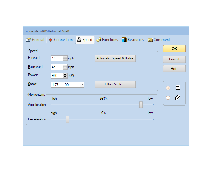
These are fairly typical settings …..its not an exact science just set the sliders for low acceleration and high deceleration. TC runs everything from the speed profile.
Its a good idea to research correct power settings. I cant help with Deltics etc
 but I have a spread sheet for LMS and GWR (and BR) power ratings by class that are fairly accurate.
To give an idea of range a 14xx 0-4-2 (BR rating 1P) is 370 kW whereas a 4-6-0 7P is 1000kW
TC takes all this into account plus the weight of the train. The difference in sprightliness between a light engine and hauling 8 loaded coaches is quite spectacular.
Hope this helps and isnt too long
John
Posted
Full Member
Anyway that there Deltic has been round the main line loop a few times, not totally without incident, but enough to let me finally have a play with the Traincontroller software. So far the known issues to be resolved are:
- One of the two Digitrax boosters insists on beeping 4 times at power up and power down
- One of the non-scenic point motors appears to want to switch both ways every time a train wants to use it
- There is a strange click at the far end of the layout at power on but I can't be in two places at once
- Two of the Cobalt point motors insist on centering at power on - sending 198 to them doesn't cure it
- There is an issue with power loss and shorting over one of the SL94 crossings
As far as the Deltic goes, my profiling blocks, lets call them A, B and C, are all around 2 metres long. So the loco starts in A, is timed over B and stops in C. So far so good, only as the speed increases the distance before the loco stops once reaching C and reversing to A gets longer and longer until towards the end of the sequence it is taking more than 2 metres to stop. I have got to be doing something wrong but really haven't had the time to spend investigating.
So thanks for the response John. I will get back with a more detailed response when I have had another play. I need to check what the loco's CV settings are as well.
Posted
Full Member
When profiling at higher speed steps the loco does take a while to stop. My run off block and start block are about 2' long and each have a padded buffer at the end. Even so from about speed step 20 on I tend to slow the loco with my hand just before it reaches the buffer to prevent it hitting the buffer with too much velocity. I could see that happening even with a 6' run off block
Good luck with your visit
John
Posted
Full Member
But as anticipated with this phase, there are successes and failures. My favourite 9F which worked fine when last run in the UK now appears happy to run forwards but shorts out the whole system when you try and run it in reverse. I was also investigated the stutter running over a crossing (Peco SL-94) only to find that I hadn't really understood how it was wired by the manufacturer - now I do - so that means the three crossings I use will need taking up and "modifying".
So along with finishing installing the last few point motors and completing the wiring the next milestone is to get one of my smaller steam engines to do a complete circuit to really test out the track (hopefully by the end of the year). Once that is done I think it would be good to do a full test trying out every loco and it's associated rolling stock around the main line and over the branch line. Once I am happy that has been achieved I might actually start some ballasting and other scenic work. I am going back to the UK in January so if I have any locos I can't sort myself it would be an ideal opportunity to take them back and get them fixed.
Posted
Full Member
Glad to hear that you are getting things sorted and that my RR&Co notes helped. Do remember though I wrote them ten years ago so some parts will be out of date.
Is the 9F the Hornby model with tender pick ups? If it is look at the contacts where the tender hooks on to the loco……the springy contacts can easily get bent out of shape and touch the wrong side of the loco contact…..this may explain the short in reverse. I found it an ongoing problem with a Grange which uses the same system. I carefully corrected the shape and insulated the underside with nail varnish.
HTH
Regards
John
Posted
Full Member
I have allocated 6 locos and carriage sets for East Coast main line passenger workings and these have been set up in traincontroller as a series of schedules triggered from a timetable. Once I get a bit further I will add in extra entries for goods traffic and branch and other semi-local passenger workings.
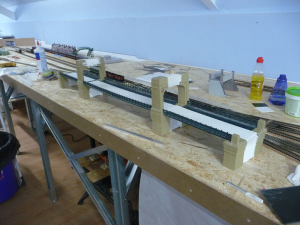
I have also taken the plunge and started "modifying" the Hornby suspension bridge. I did ask about even attempting it and was advised it's probably not worth it but given it was in my stock and there was no way I was shipping it back to the UK and trying to sell it, I thought why not. Anyway here is a couple of photos of progress so far.
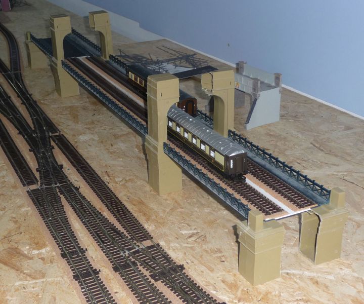
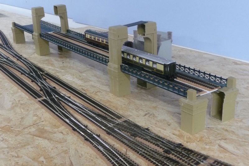
It needed to be double track and shorter. So I have made it wider with plasticard and shortened each of the four bridge sections. I then split the supports to accomodate this. I have also run square section aluminium beams both sides through the supports to help with strength. So the bed shortening and widening has worked out fine but the real test will be the pillars. My plan is to continue with the double layer plasticard method to bridge the gap and, when ready, spray them with a concrete effect slightly textured spray paint.
Posted

Site staff
Ed
Posted
Full Member
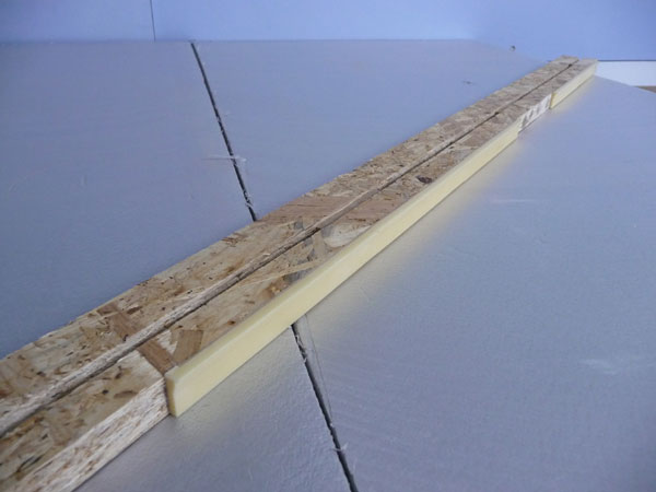
1. Making a double track, double girder bridge. New cross pieces and bed made now just need to make the supports. I am planning to use OSB internals with modelling clay wrappers scribbed as stone work. One at either end and one in the middle.
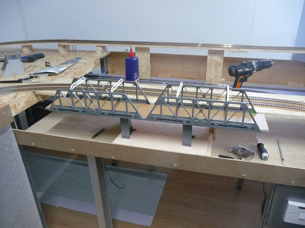
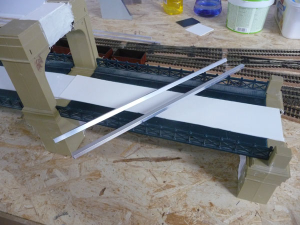
2. That ????? suspension bridge (shortened and made double track). The jury is still out - it may yet get put in the bin. The bed is all ready to be glued in place and painted but, as I was advised, the supports are going to take a long time. You will see on the second picture the aluminium section I have cut to provide structural support, it fits very nicely under the bridge on each side.
3. Ballasting. This is going to take months if not years but I will just pick away at it now and again. I am using a mix of Peco grey fine ballast and Legacy brown ballast although after glueing it is coming out darker than I was anticipating. Now what I really could do with is the club tub from DCC Concepts but postage here to Spain makes it a bit prohibitive - may have to wait until I drive back later in the year.
4. Station platforms. The basic idea is to glue on the edgings onto the OSB pieces and then pad the centre out as appropiate to get the platforms just the width I want them, which allows some slight variation between platforms to get the carriages to run as close as possible.
So that's the progress. The backward step is a couple of sections of ID backscenes I had put on before going on holiday. I came back to find they had started to come off and were basically trashed. Ah well back to the drawing board on that one.
I also placed an order for another couple of Deltics being produced by Accurascale. That should allow me to run all 6 front line passenger expresses with Deltics. I really must stop buying locos though - there is only so many sidings on the layout!
Posted

Full Member
I've heard that, perhaps counterintuitively, it's quicker and easier to ballast in small sections.
Last edit: by ZeldaTheSwordsman
Posted
Legacy Member
Very good idea with the split platform boards to allow for varying widths does the osb give you the correct height once you have put the platform top on?
I am using the DCC concepts legacy ballast i am very pleased with it and yes the 5 litre tubs are the best way to buy it i bought 2 and you do get 5 litres of ballast in it.
Brian
OO gauge DCC ECOS Itrain 4 computer control system
Posted
Full Member
Not sure I am looking forward to trying to make the girder bridge supports - talk about way outside my comfort zone - bring on main board construction and electrics any time.
1 guest and 0 members have just viewed this.