OO Gauge - Latton Fields
Posted

Banned
Branch Line - Roundy, roundy with some shunting
Looking good Ed. :thumbsI know this advice is a little late, bu I used a circular saw set at approx. 3mm 1/8th" deep to cut slots in the baseboard to run wire in tube from the side of the baseboard to the centre of the points. It does mean laying out the track and marking all the slot lines, then lifting the track and cutting with circular saw. You could always use a dremel or similar to cut slots as well, if you don't have a circular saw at hand.
Cheers, Gary.

Posted

Site staff
The Funky Foam underlay raises the track 2mm which is enough for running the point control rods and any surface wiring, but I do agree a slot in the base board would have really been the ideal way of doing it.
Ed
(PS: No, haven't got a circular saw, haven't got a Dremel or equivalent either. Not saying what I use to cut track :roll:)
Posted
Guest user

Cheers
Matt
Posted

Full Member
Marty
Posted
Site staff
Right, on to a secondary project.
I have been thinking for some time that an additional throttle would be useful in the future operation of Latton Fields, but at £58 for a Digitrax UT4 Utility Throttle it became a very low priority. Although I did follow an auction for one on that internet auction site, but it ended up nearly the same price.
However, as my Digitrax Zephyr Xtra DCS51 has the feature of allowing up to two (smooth) DC controllers to be used as additional throttles, I thought there may be a cheaper solution.
Although I still have my Gaugemaster Model D, used for point motor control and lighting, I felt it may be a bit 'too good' to be used as the additional throttle.
Quoting the Digitrax Tech Support Depot, “ Note: Many power packs have automatic pulse injection, which should not be used in this application. Check with the power pack manufacturer if you are not sure. There is no list of appropriate throttles, but, in general, the more expensive the power pack is, the less likely it is that it can be used in the Jump Port application.â€
I have read that the square white Bachmann train set controllers are know to work well, but they also are around £30.
I also joined the Yahoo Digitrax Users Group and posted a query there, but have had no response. They do have some plans for building a suitable controller for use on the Zephyr's jump port but they appear to be a far more sophisticated types of controllers and a bit beyond my electronics knowledge.
I can't quite believe it's been eight months since Gormo's posts about building a hand held transistorized controller for use on Great Chesterford, but after reading them I thought this may be a solution.
http://yourmodelrailway.net/view_topic.php?id=11121&forum_id=21&highlight=controller#p220649
After searching the web I found Tony's Train Exchange old website has instructions for a push button version, but the plan still looks a bit complicated to me.
http://www.tonysdcc.com/technews/zephyr-cab.htm
Further reading suggested a battery powered controller, which is smooth DC, may well fit the bill as the battery isn't actually controlling the loco, just supply a variable voltage to the Zephyr's jump port. It's the Zephyr that powers the track and sends packets to the loco decoder, depending on the voltage of the battery controller.
I found an old web site belonging to Timothy André, whoes railroad section Firebaugh Rail Lines (last updated 2008?) has the simple type of battery controller I wanted.
http://www.tandre.net/Trains/Firebaugh/Current/JumpThrottle/index.html
Like all additional projects this has sat on the back burner for some time, until a couple of weeks ago I bought the required bits for less than £10.
It's very similar to Gormo's controller, except using a battery there is no need for any diodes i.e. bridge rectifier.
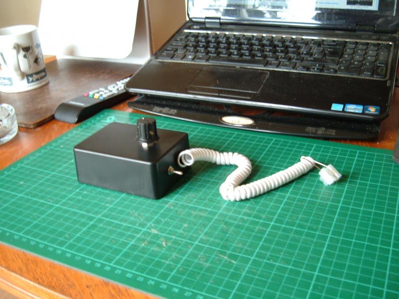

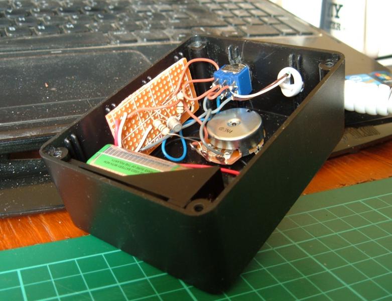
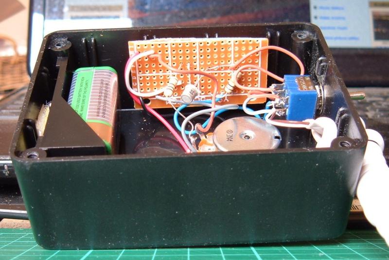
The innards
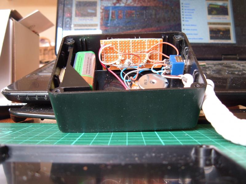
Just connects to a jump port.

The Jump key on the Zephyr cycles through the jump ports allowing locos to be assigned to the Zephyrs throttle and the throttles on jump1 and jump2. The second green light from the left means jump port one is assigned loco address 34.

Works as well!
http://www.youtube.com/v/RWjP47CNo0Q?version=3
Being only a 9v battery, you can't get top speed, but it doesn't matter for shunting and the pugs go too fast anyway.
(Must get around to changing their CVs).
Ed
Edit (PS: Sorry about the different fonts, it's not me Guv, it's copying and pasting from LibreOffice what done it)
 Last edit: by spurno
Posted

Inactive Member
What a clever cost effective idea. I am completely ignorant when it comes to DCC but even so, I can see the merit in what you`ve done there.
Well done Sir.!! thumbsthumbs
:cheers Gormo
Last edit: by spurno
"Anyone who claims to have never made a mistake, never made anything!!"
https://sites.google.com/site/greatchesterfordmodelrailway/home
https://sites.google.com/site/greatchesterfordmodelrailway/home
Posted
Site staff
Ed
PS Think you ought to give a name to all these little ideas and inventions you come up with, how about 'Gormo's Gizmos' ?
Posted
Full Member
Bravo
Marty
Posted
Guest user
diving into the dark side a bit there. over my head I'm afraid but sounds like its well thought out and developed.
well done.
Toto
Posted
Inactive Member
That sounds like a name that will stick!!!…….thanks Ed…..I will use that from now on.
:cheers Gormo
PS….pardon my ignorance….but if you set the CV for your little pug…..can it be set to a maximum and minimum speed???……and therefore your new hand made controller will only have control over that range????……so for shunting you can have the little engine say at scale walking pace????
Last edit: by spurno
"Anyone who claims to have never made a mistake, never made anything!!"
https://sites.google.com/site/greatchesterfordmodelrailway/home
https://sites.google.com/site/greatchesterfordmodelrailway/home
Posted

Site staff
While I am into DCC - NCE, I do think your idea Ed is first class and deserves one of these :patheadG`day Ed,
What a clever cost effective idea. I am completely ignorant when it comes to DCC but even so, I can see the merit in what you`ve done there.
Well done Sir.!
:cheers Gormo
Last edit: by spurno
Ron
NCE DCC ; 00 scale UK outline.
NCE DCC ; 00 scale UK outline.
Posted
Site staff
I'm happy with it and I think I might make a second since there is another jump port on the Zephyr.
Theoretically your right Gormo about setting the CV's for just shunting (or as our US cousins say switching) speed range, but the motors in the little pugs aren't that good at slow speed control. One of the two I have is much better than the other, yet they are both reasonably new.
They meet my needs, but better models with better motors would be far more controllable, whatever throttle is being used to control it.
Ed
Posted
Inactive Member
Those little pugs are like a couple I have with the slot car motors and they go like stink. I have one that is racing as soon as it starts almost. Pity they aren`t geared a little better for slower speeds.
Oh well there you are???
:cheers Gormo
Last edit: by spurno
"Anyone who claims to have never made a mistake, never made anything!!"
https://sites.google.com/site/greatchesterfordmodelrailway/home
https://sites.google.com/site/greatchesterfordmodelrailway/home
Posted
Site staff
Takes a bit of voltage to overcome the magnets and get going.
One of mine was always better at slow speeds under DC and I did play around with back EMF and CVs a bit when I converted them to DCC and they both improved at slow speeds slightly, but one was still better than the other.
Since then I've reset the decoders a few times for other reasons and their both back at the defaults.
Haven't got around to adjusting them again and as their good enough for my use, I may not bother.
(Another 'back burner' job).
Ed
Last edit: by Ed
Posted
Site staff
Peco code 100 electrofrog points instructions state "There is no need to modify any PECO turnout for DCC use†and although they do mention cutting the links and using a switch for the frog, there is no mention at all about linking the closure rail and adjacent stock rail.
The same is true for the instructions on their website for OO/HO Gauge Electrofrog Turnouts/Crossings
http://www.peco-uk.com/imageselector/Files/Instruction%20sheets/HO-OO%20Electrofrog%20Turnouts.pdf
However, if you look on their website at the link for OO/HO Gauge Concrete Turnout (Code 75)
http://www.peco-uk.com/imageselector/Files/Instruction%20sheets/Code%2075%20Concrete%20Sleeper%20Eng.pdf
Lots on here say add links between the closure rail and adjacent stock rail and don't rely on the switch rail blades for electrical connectivity, weather using code 75 or code 100 track.
Lots of people also say they haven't done anything to their Peco electofrog point and have had no problems, and it is interesting that the newer versions no longer have the little flexible tab on the end of each switch rail, inferring the contact between the switch rail and stock rail should be all that is necessary.
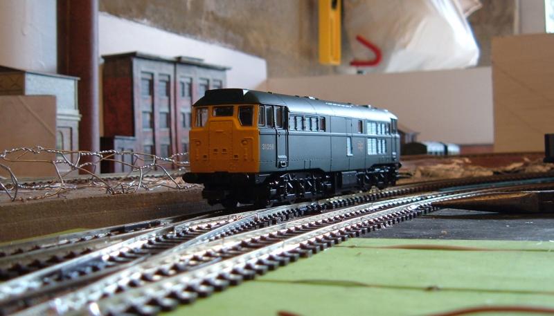
I've so far laid five electrofrog points and two have had no problems at all. Two have caused my pug (testing loco) to stall, but after switching the point a few times they're fine. Being in the garage it's not exactly a clean environment, so I was expecting to have to clean all track quite frequently.
This last one doesn't want to play.
Didn't matter how much I switched it, cleaned the switch rail or pulled on the tie bar to try and get good contact via the switch and stock rails, the loco stalled.
Placing a small screwdriver across the switch rail and adjacent stock rail, all was fine.
The solution …………
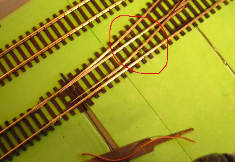
As much as I didn't want to cut webbing and unintentionally melt sleepers by inserting links, it's definitely what needs to be done, preferably before laying the point.
I'm working my way around the others now inserting inks and the two I have left to do will have links before I lay them.
My humblest apologies to all those who said you do need to do it, it's a case of 'It doesn't always do what it says on the tin'.
Ed
(PS doing me best not to melt sleepers. Noticed the magnifying visor help when I remember to use it)
Posted
Guest user
its a pita but I've done the same on every set of turnouts. The only difference is that I have extended the links down under the baseboard in order to provide another track feed and not rely on power passing from either side of the turnout via rail joiners. You have done the hard bit already in soldering the link all you are doing is leaving a bit of length on the wire and taking it below.
Don't know if I am clear enough the way I've described it there but if not. I'll post up a picture of the mods the way I've done it.
good luck anyway, there should be no problem now for you.
cheers
Toto
Posted
Site staff
I would guess that Peco assume code 100 rail being slightly bigger will work without the links.
They're WRONG!
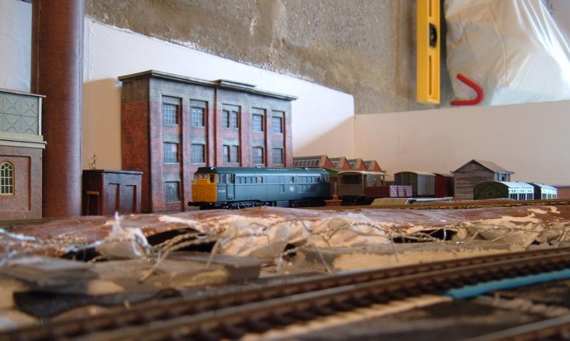
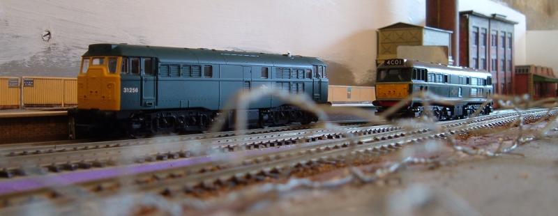
Talking of code 75, on a more successful note I bought a length on code 75 track a while back for testing and decided I'd use it for the coal siding. Being a slightly lower profile, it's easier to bury in the coal yard and is lower than the main line track.
I tried SL-112 joiners when laying the diamond crossing, but they weren't very good and ended up using four SL-113 transition tracks, which aren't cheap.
So how to join the coal siding to the goods loop? Then I remembered something Sol had posted a while back.
http://yourmodelrailway.net/view_topic.php?id=9952&forum_id=6&highlight=code+75+to+code+100#p181685
Worked a treat. (sorry about picture quality, but it's difficult to get the camera in the right place on this section of the layout).
The pliers point to the join.
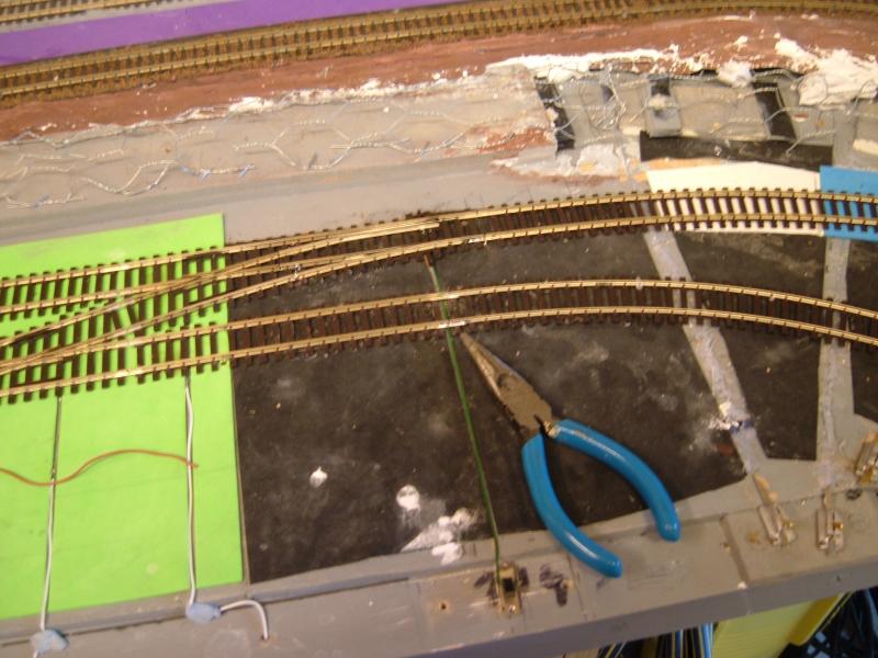

Thanks Sol :thumbs
Ed
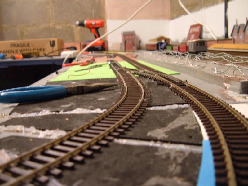
(PS You can see my chicken wire framework in these pictures Toto)
Posted
Guest user
yes I can see the chicken wire and I think it depicts one of the things that I like about it. The fact that the finished shape is more irregular. When does the cover go on ? and what will you be using. If its paper towels and PVA do me a favour and monitor the drying time. I know that there are a few comments with regards to this but most of them are with cardboard lattice work or wood. Could be interesting. I'll do like wise when I get around to it.
cheers
Toto
Posted
Site staff
First bits I did were with cheap 'J' cloths soaked in Plaster of Paris.
It was OK, but the P of P dries very quickly, so I ended up having to remix some before I got all your bits of cloth over the frame.
This time I've bought some of this ……………
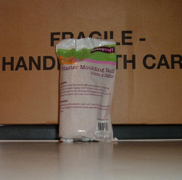
Just £1, so a lot cheaper than the Mod Roc version available from model shops.
As to when I'll do it…………………………………………. when it gets warmer, I ain't putting my hands in a bowl of water out in the garage just yet
Ed
Posted
Site staff
I've still got the very old Hornby version bought from 'the bay'. ( All Aaron's fault)

All I've got to do now is get some green paint and study new04db (Aaron's) thread on detailing.
Another job for the back burner.
Ed
(I am rapidly running out of back burners)
Last edit: by Ed
1 guest and 0 members have just viewed this.