Johns 7mm Layout
Posted

Full Member
First step was to establish our radii. We need two left radii and one right. These turned out to be: 8', 12' and 10' respectiuvely.
I used the flex track that we curved to calculate the radii using the chord and segment method. (Measure from two points on the curve to get chord and then the distance from the chord center to get the segment. Plug these into your circle calculator: http://www.1728.org/circsect.htm).
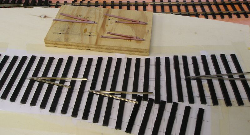
After some faffing about and realising that there is no "off the shelf" curved 3 way turnout template, I used a simple idea from Rice.
I made a left curved turnout template with 8' and 12' radii respectively, then a wye with 12' and 10' radii. I cut the common track in half and taped the two together, being careful to maintain gauge. This seems to work well.
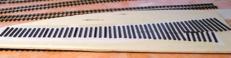
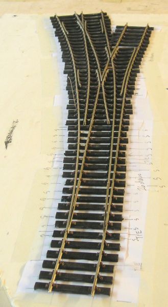
I spent much of yesterday gluing timbers to the template:
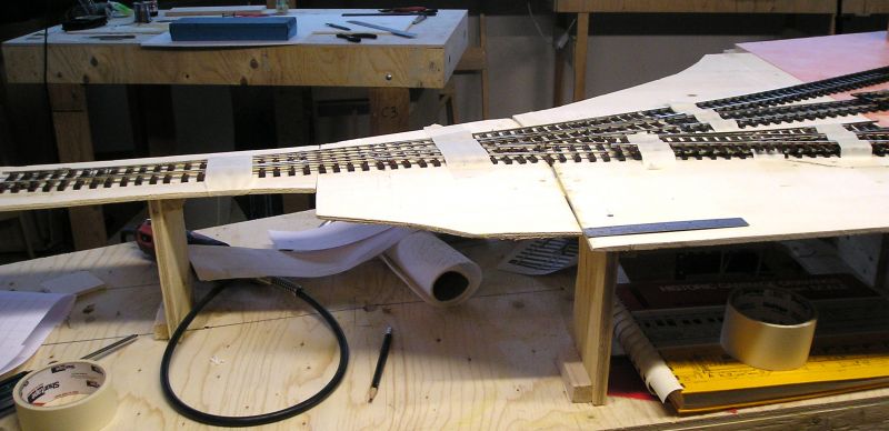
This morning I placed the template in position and overlaid some track templates of the appropriate radius, to get a clearer sense of where things are going:
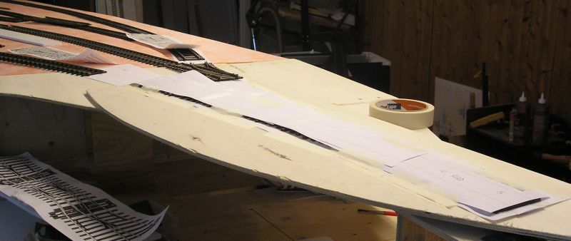
I all looks well I think.

I'll make one turnout at a time, fix and confirm we like it before going on to the next. There will be some RTP turnouts but I like the idea of a curving layout.
BTW, for those who want to make their own turnouts, you can't do better than these books:
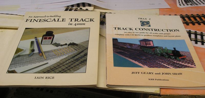
Trax2 comes with track planning program. Sort of a poor mans Templot.
John
 Last edit: by Brossard
John

Posted
Full Member
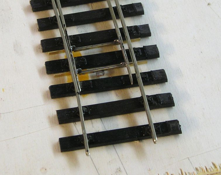
Here's a cruel close up of one of the vees:
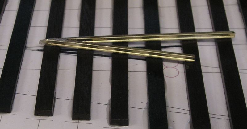
There is a bit of art to it. The front of the vee is planed slightly and the nose rounded over to give wheels a smooth transition.
John
John
Posted
Full Member
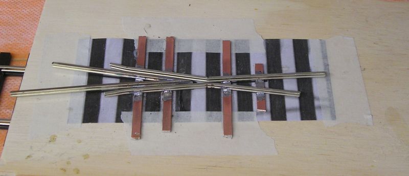
I photocopied the template at the location of the crossing. This tells me where the timbers go. I taped the copy to a scrap piece of ply and glued down strips of copper clad strip in between the timbers. I have a ton of this stuff left over from my 4mm days.
After that I soldered on the vee making sure the nose is over a timber. I then shaped the wing rails making sure the knuckles line up with the vee. This took a few tries on the first one but I got better as I progressed. There should be a sight line along the wing rail and through the vee. Wheels must go through this smoothly and it is the key to a successful turnout.
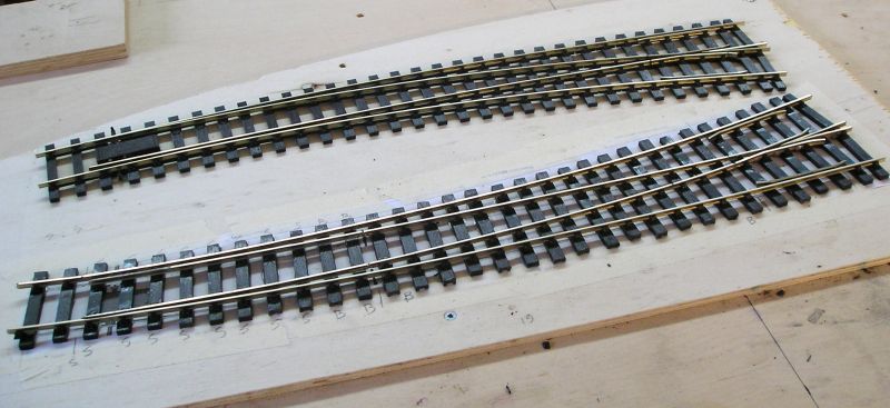
I completed the othe two, removed them from the template and trimmed them:
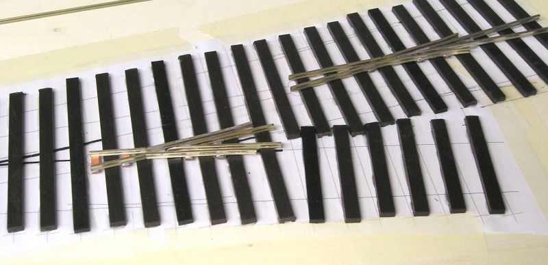
Just a matter of joining everything up.
John
John
Posted
Full Member

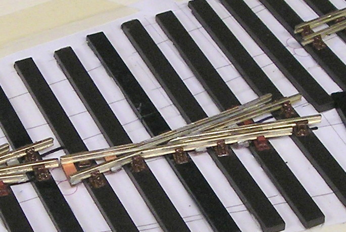
I had to redo the leftmost crossing and sharpen the vee angle in order for it to line up with the other two.
Here's a closer look:
John
John
Posted
Full Member

The plywood to which I taped the template was warped so I screwed it down to another layout board to keep everything flat. To that end, I added weight as I added rail to ensure things were kept flat as the solvent went off.
As far as I can, I have tested that the crossings work, so quite pleased.
I've done two blades so far and have two left to do.
I've also got tiebars to install. I want to do better than the old copper clad strip and have some JLTRT etched tiebars. Never done that before.
I'm also using Exactoscale lost wax brass fishplates as can be seen at the heels.
John
Last edit: by Brossard
John
Posted
Full Member
Mine doesn't have rebates for the blades and uses cast brass fishplates for the heel connection to the blades. I'll do the tiebars later.
Loose heel blade connection.
John
Last edit: by Brossard
John
Posted
Full Member
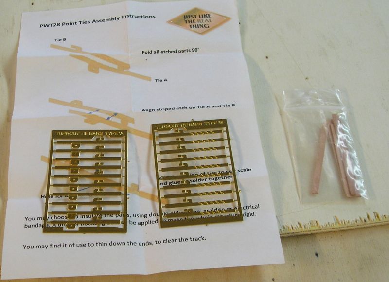
These are JLTRT etches. I'm using copper clad strip that I got from C&L. Now JLTRT shut up shop last week and C&L is not what it was since it changed hands.
The idea is to make a sandwich with each side of the tiebar and copperclad. Apart from spacing the blades apart, the tiebar must be insulated. I didn't fancy using glue.
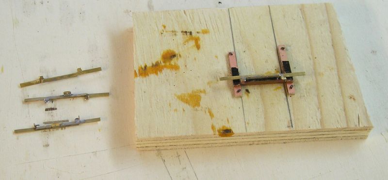
I made a jig to help me space the tabs to a constant length - 27mm seems about optimum based ona previous turnout I made that I know works.
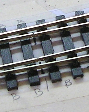
You can see the tiebars made up for the 3 way turnout, 2 tiebars per switch.
First pair installed, these look much better than that nasty old copperclad thing. You can see a tab in the middle of the first tiebar. The pin from the motor (Tortoise) will go in that.
John
John
Posted
Full Member
The 3 way turnout forms the throat. The left most road is to the engine shed, center to the station and right to the goods and coal.

In this view the shed can be seen on the far left. The box infront of the shed is an ash pit.
The two tracks for the station are next. I made some 57' templates for Mk 1 coaches and these define the station platform length. There will be a milk bay where the tanks can be seen.
The Cl 15 is about as long a loco as I will have so it defines the length of the release. I made sure to allow for the length of buffer stops.
Next can be seen the parcels bay currently occupied with an autotrain.
Behind the station bldg. is a small cattle dock - the cattle van indicates that.
The goods line is to the right with a small goods shed. There appears to be room for road vehicles.
The rightmost line will feature some coal drops for commercial use.

A slightly closer picture of everything.

Finally a look down the layout. I'm quite pleased with how things look.
John
Last edit: by Brossard
John
Posted

Full Member
Neat home-brewed tie bar design.
Nigel
©Nigel C. Phillips
Posted
Full Member
I'll have a pause for a bit now until I get the team together for a conflab. I also have some wooden timbers on order so will wait for those before constructing more turnouts.
John
Last edit: by Brossard
John
Posted

Full Member
What excellent cumulative progress which can now be appreciated through your latest photos. You must be pleased, as all your planning is producing a splendid looking railway.
Is that the Dapol autocoach? I saw one at a recent exhibition, in GWR livery and was so impressed, that I very almost came home with it! The extra detail capable through 7mm scale is breath-taking and your post shows the roof detail very well.
You have my full attention and I'll have my new tablet next to my work bench to follow progress.
Best,
Bill
At 6'4'', Bill is a tall chap, then again, when horizontal he is rather long and people often used to trip over him! . . . and so a nickname was born :)
Posted
Full Member
One of the things that attract me to this scale is the ability to add more detail.
Happy to hear that you'll be in the audience.
John
John
Posted
Full Member
Here's the result:

I removed the three timbers beneathe the box. I then removed the blades and cut the pivots off. The loose heel connection on teh Peco T/O is a rail joiner, this was filed and cut away.
I used C&L timbers and Peco slide chairs to replace those that I had cut out.
C&L cast brass fishplates were used to give a more realistic representation of the loose heel.
The tiebars were discussed earlier. They are a faff but look pretty good.
The only thing I couldn't do anything about were the stock rail rebates for the blades.
The gaps between stock rail and blade are pretty large but necessary I have found to cater for the FS specs.
Now for the other one. :roll:
John
John
Posted
Full Member
Over the last couple of days I made these:
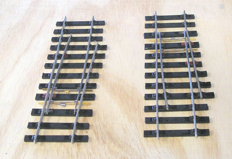
Standard turnout building techniques without the need for a common crossing. I will probably install a Tortoise underneath, that way if we are really feeling keen we can follow prototype practice. Hope that this doesn't happen:
John
John
Posted

Full Member
"The only stupid question is the one you don't ask"
Regards.
Tony.
Regards.
Tony.
Posted
Full Member
John
John
Posted
Full Member

I got the gap to be ~2.5mm vs 3.5 - 4mm before. I was careful to check with a wheelset to confirm that the flanges don't collide with the blade tip.
I wish I'd read Jims article in MRJ 99 about making 0 FS gauge (32mm) turnouts more realistic before. In a similar fashion to 00 SF, the key is reducing gauge through the turnout to fine up flageways and blade gaps.
There are 3 sub gauges: 0-MF - 31.5mm gauge, 0-SF - 31.25mm gauge and 0-XF - 31mm gauge. These allow the use of existing wheelsets. You do need specific roller gauges for easch sub gauge. There is only a need to gradually reduce the gauge of plain track leading to the turnout. Fascinating stuff.
Over the last day, I have refined the other turnouts that I built so we now have a good baseline.
John
John
Full Member
Things have moved on a lot since my last post. The layout is running superbly and has even attended two shows. Scenery is still lacking but in the last few weeks I've been working on that with priority for ballasting. Once I have tidied up a bit I will post some pictures of where I am.
In the meantime, here are a few recent pics:

This is one of my favourite views and gives a great perspective of the layout.

Lovely overall view of the layout at Exporail during their model train weekend. A great museum if you are in the Montreal area.

Class 15 diesel (LLC) with mixed freight.

J50 (Finescale Brass) with a mixed freight. WR autotrain is in the bay, both vehicles are from Dapol.
You'll note that there are green pushbuttons on the fascia. These are momentary and activate the point motors which are powered by Wabbit stationary decoders.
Buildings: I am a huge fan of Scalescenes. Some of the buildings are Scalescenes kis such as the creamery on the left of the first picture. To the right of the first picture are Scalescenes Terraced Houses, Corner Shop and Garage.
Most of the other buildings are LCut. I modified these heavily uing Scalescenes elements such as brick and roofs.
Cattle dock is from Skytrex with a scratchbuilt base.
Finally at the right of the first picture is the Station Masters house which comes from Finescale Buildings. Excellent downloadable kits, sadly gone now.
Cheers all, I look forward to chatting further.
John
John
Posted

Site staff
Good to hear from you.
Things certainly have moved on, looking good 👍
Ed
Posted
Site staff
Regards
Alan
Born beside the mighty GWR.
Alan
Born beside the mighty GWR.
1 guest and 0 members have just viewed this.