Johns 7mm Layout
Posted
#221059
(In Topic #12054)

Full Member
http://yourmodelrailway.net/view_topic.php?id=14385&forum_id=5
I decided I'd better get on with building a layout. Now, originally I had planned to do something in 4mm, 00. However, over the last couple of months I have been more and more drawn to the allure of 7mm. The presence and heft of stock and the opportunity to add more detail is very appealing.
Initially I had thought to work in both scales but then after more thought, I decided that it made more sense to focus on 7mm, so I'm going all in and my 4mm stock is up for sale
I have started to build a kit of a brake van here:
http://yourmodelrailway.net/view_topic.php?id=14578&forum_id=150
…and made some buildings here:
http://yourmodelrailway.net/view_topic.php?id=14475&forum_id=150
So, one step at a time. Over the last weeks I have been gathering track and track components.
I bought some C&L flexitrack but the charges were eye watering :shock: since it has to come FedEx being oversized. I found someone over here that keeps Peco 7mm track in stock so I've now got roughly 20 yds of flex track. One worry is that when mixing brands of track the height won't match - not so here, the C&L and Peco track lines up perfectly. The only difference I can see is that sleeper spacing is a bit less on the Peco track, but not nearly as pronounced on 00 track.
I've also got timbers and chairs from both C&L and Peco. I did spend a fair bit of dosh, roughly the same as a RTP Peco point, on a complete point kit from C&L. This comes with a made up common crossing (vee and wing rails) and planed blades. There's also in instruction booklet and a template. I won't need to do that again so my turnout costs are going to be quite low. BTW a Peco point is around 69 GBP.
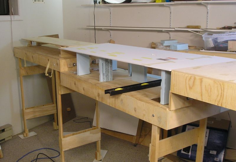
Yesterday, I thought I'd start by trying to get a feel for where the track would go if I had a traditional fiddle yard and point ladder. There's a sunken section, so I used foam core board and foam to built that up to the track level. I then laid out track and Peco point templates to see what's what.
Here's what I found:
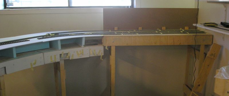
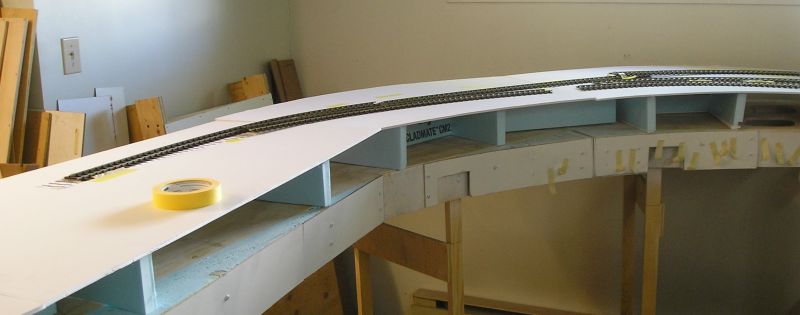
I found that the fiddle yard to the right of the first picture can accommodate three tracks which would require just two points. However, to avoid baseboard joins and to have track flowing with reasonable radii, the first point would need to be located in the middle left of the first picture. The second point would have to go where the last piece of track is located on the second picture.
This is where I stopped because it is crystal clear that this arrangement won't do. It takes too much room and too much track. My conclusion is that I will therefore have to build a sector plate.
I will document my progress.
John
John

Posted
Full Member

Center
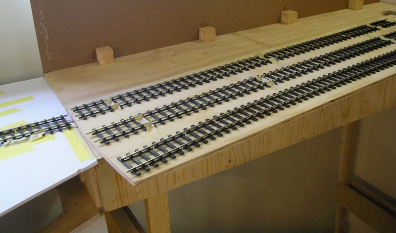
Right and…

Left.
Pivot is at the far end and the plate is radiused to swing without hitting the wall.
The transition end is also radiused such that the right and left tracks are curved to be parallel with the main track. I did this by empirical determinism.
The plate is just about 4' long and will hold a small loco and two coaches.
Next the board and indeed, the whole sunken section will be dropped by ~ 4" so that I can do a road underbridge beneath the track.
John
John
Posted

Full Member
Posted
Full Member
John
John
Posted

Full Member
That makes a change!
Nigel
©Nigel C. Phillips
Posted
Full Member
John
John
Posted
Full Member

I also cut the foam core to the width of the raised roadbed, the dimensions for which I took from Bob Essery's book on Signalling and Track Layout.
A hot glue gun is useful for fixing the foam to the board. I got a dual temp gun with a lower temp for foam.
I can start roughing in the main part of the layout next.
John
John
Posted
Full Member
Unless you're planning on some short wheelbase 0-4-0's, you'll probably need radii greater than 36" (think 18" radius in OO). One of the issue I had when doing On30 was the mental switch necessary in going from 4mm to 7mm scale. Often fell into the trap of laying track to 4mm specs and then finding that a 7mm model careering around the bends was a bit incongruous, even in narrow gauge. Gentle curves look much better than sharp corners.
My experience with white foam board is that hot glue sticks to the white coating powder, not the board, and it comes apart after a few months. Looks like a temporary construction (I hope).
Nigel
©Nigel C. Phillips
Posted
Full Member
Everything is mocked up and will be replaced by wood once I'm satisfied with things.
Thanks
John
GOG says that for light railways or shunting layouts running short wheelbase locos, 36" is min. For branches running locos with wheelbase of 16' (typically a 0-6-0) then 48" is min. Certainly radius matters a lot when propelling loose coupled vehicles because of buffer lock. The recommendation is to make buffer heads larger (as in life) when shunting small radius curves.
I'm a bit hobbled by not having a loco to work with.
 Last edit: by Brossard
John
Posted
Full Member
So, I've dismantled the curve and will rebuild the layout to be straight. This process is going on as I write and I will take pictures when things are settled.
John
John
Posted
Full Member
Multi-tasking again then. One hand on the saw, the other on the keyboard.
You can always put a slight curve in to give a bit of scenic interest. At least with a linear set-up you can keep an eye on what's going on down t'other end.
Nigel
©Nigel C. Phillips
Posted
Full Member
John
John
Posted

Full Member
Cheers
Posted
Full Member
John
John
Posted
Full Member
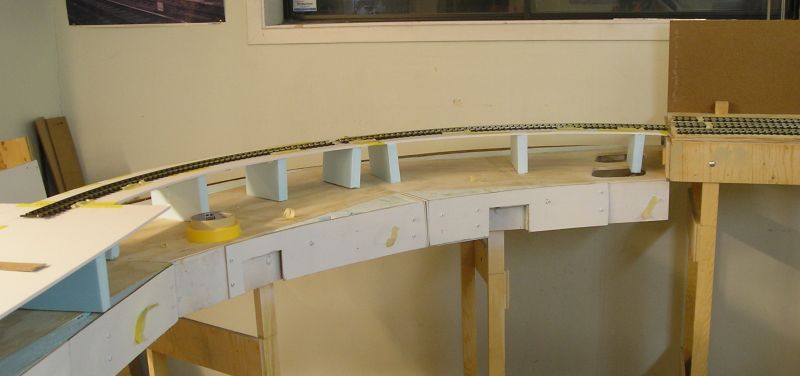
Sector plate module at the far end. This is pivoted at the far end end and will hold three tracks.
I increased the depth of the sunken module to 8" which is more appropriate than the previous 4" for this scale.
I made a mockup to allow me to place track and see where things go. I'm visualizing that the rear half of the module will be at main module height and that things will fall off towards the front. I'm also visualizing a bridge with a road/canal underneath.
The layout is now angled and its' length is ~19.5'. There is a comfortable gap at the opposite end that makes it "old person friendly". Even though I can still manage to clamber under baseboards, it's no fun.
John
John
Posted
Full Member
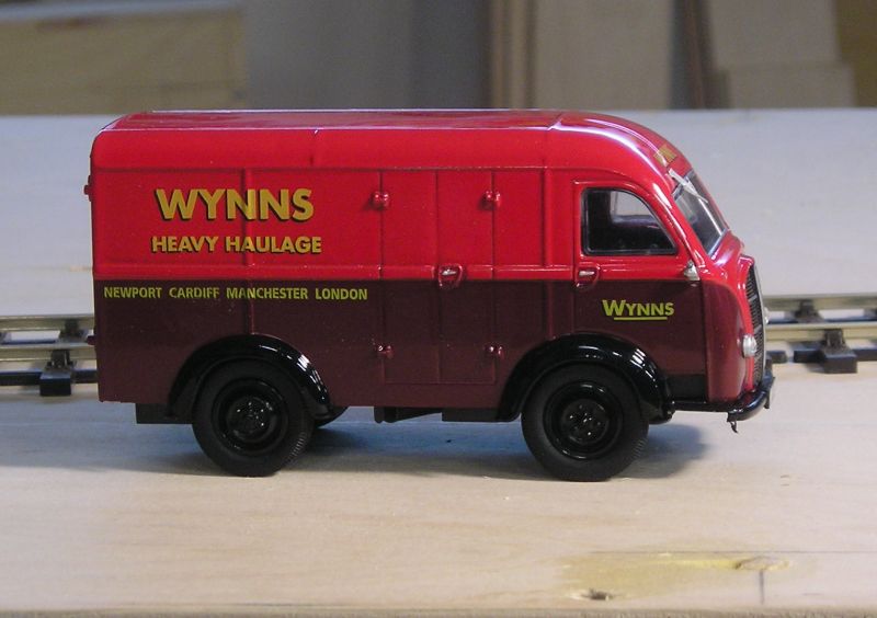
Austin K8 and…
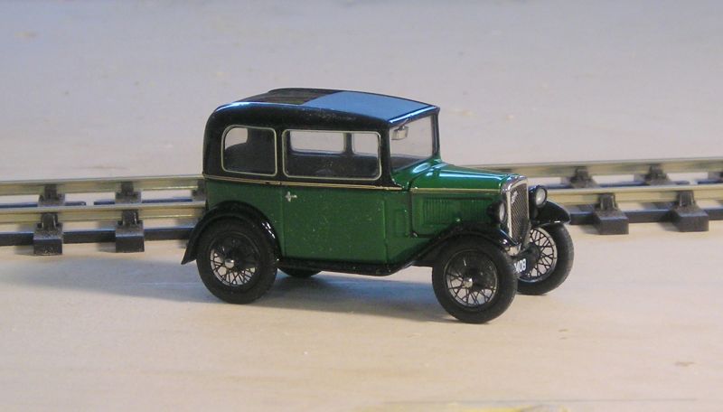
Austin Seven. A bit long in the tooth perhaps but I imagine there were still a few about in the 60s. I will keep my eyes peeled for more family cars.
John
Last edit: by Brossard
John
Posted
Full Member
What we found however, is that we needed two RH turnouts that were not ordered and that a curved turnout was redundant. A deal was made such I would make two RH turnouts and, in return, I would get the curved turnout.
The basics are shown here:
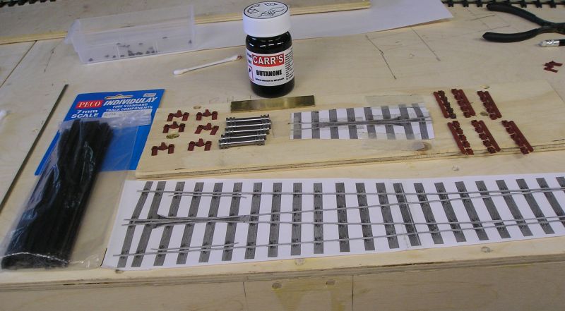
Peco do turnout construction components for O gauge (Individulay). I have rail and timbers. There are two kinds of chair, slide (to support the switch rail) and running (for everywhere else). I have numerous roller gauges (can't have too many) and I made a flangeway gauge by gluing two lengths of brass together. The Peco template is shown. I also cut out a template for the common crossing which is made separately by soldering rail to copper clad strip. This makes a robust sub assembly for the heart of the turnout. Everything else is gauged from this.
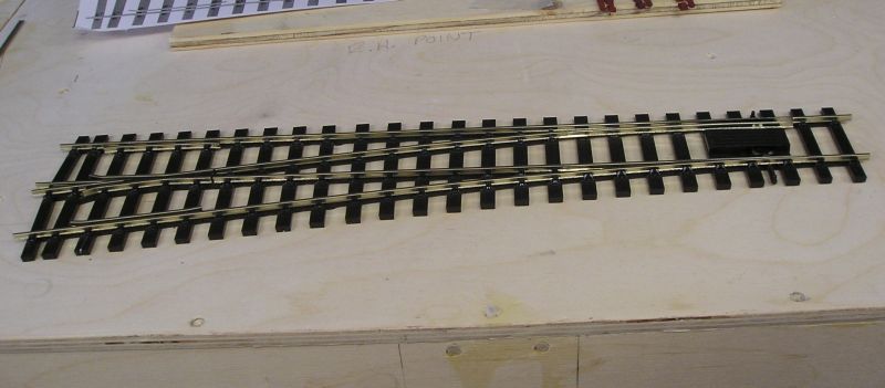
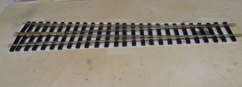
So, here's one I made earlier:
Steps:
Lay out the timbers and cut to length. For those timbers that take slide chairs I used Tacky Glue to stick them to the template. I will leave this part of the template with the turnout, cutting out around the timbers. For the rest I used double sided sellotape - the cheap stuff. You want to be able to unstick the turnout later without damage.
Position the common crossing and secure with chairs. The recommended solvent is butanone.
Use gauges to place the straight stock rail, sliding chairs on and making sure they are positioned over each timber. When this is on to your satisfaction (and straight!), add the slide chairs. Be sure and file a rebate in the stock rail to take the end of the switch blade.
Do the same with the straight closure rail, then curved stock rail and closure rail.
Switch rails take a fair bit of carving. I used my Dremel with a grinding wheel to remove most of the material, finishing off with coarse and fine files. Not that difficult but the planing has to be the right length along the rail to avoid fouling the stock rail.
Almost complete, I just have to add the tiebar. For that I want some brass pins to act as hinges on the tie bar. (BTW the chairs are reddish because I hated the black on black which I find difficult to see. I sprayed all the remaining chairs red oxide primer to enhance contrast.) The switch rail is connected to the closure rail with a code 100 rail joiner (loose heel). I will solder one end of this and add an omega loop to the two ends for continuity.
Now that I think I know what I'm doing, I can show the steps in more detail.
John
John
Posted
Legacy Member
I bought one of these (Austin 7) for a fiver off a pub landlord in Marston Mortayne, Beds for a fiver in 1960.…and a bit of fun. I was trolling Hatton's last week and these caught my eye:
Austin K8 and…
Austin Seven. A bit long in the tooth perhaps but I imagine there were still a few about in the 60s. I will keep my eyes peeled for more family cars.
John
The tank was full of water but when drained, filled with petrol and swung a few times, it fired up and then I drove it all the way to LLangwern steel works, Newport, where a week later I sold it to the site foreman for a quid.
Wish I had it now instead of my Benz 500 SEL - a lot slower maybe but bags more character.
Allan
Posted
Full Member
John
John
Posted
Full Member
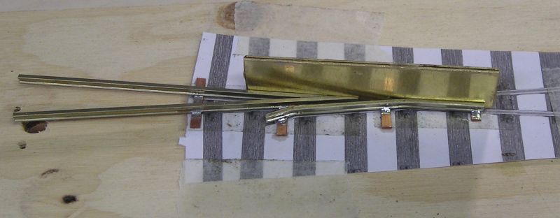
This shot shows the sub assy on template. Copper clad strips are located at strategic places. The flangeway gauge is important to ensure that the vee and wing rails are aligned - a crucial bit of geometry.
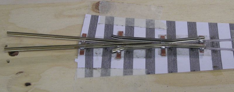
Flangeway gauge removed. Note the knuckles of the wing rails must be directly opposed to each other.
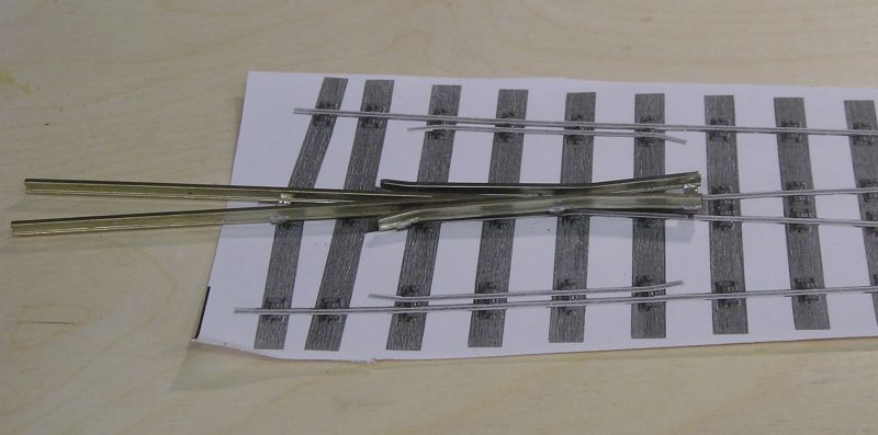
Crossing laid on the turnout template. Excess copperclad strip trimmed away.
John
John
1 guest and 0 members have just viewed this.