John Street - BR(E) - 1960
Posted

Full Member
My second bash at model railway-ing
Thanks Tony.And yes I have been asking around about motorizing the turntable - and have seen various measurements surrounding the Locomotech motor. Generally, from what I've seen, the diameter comes in at various measurements of around 30 - 40mm dia with a length of around 110mm. And I've heard good reports about it being quiet and slow. Your take on the measurements would be appreciated if it's not too much trouble.
I would be ok at manually eye-lining it up at the entry point (near direct line of sight) but at the exit to the shed, at around 100deg, might not be quite so easy from the operating position. Plus the fact I like things to be as automatic as possible rather than relying on, what will be in years to come, a gradual failing of eyesight. The eyes are ok at the moment, but the years, I am sure, will be taking their toll soon enough.
I've also been looking at the small, cheepo far eastern motor (which I already have) and how to drive it - using a sensor to create a "start" point and to calculate the number of turns of the motor shaft to get the T/T from position "A" to position "B", etc. But I'm not sure if the motor - or my programming skills (if you can call them that) - would be up to job.
Then there's reports on the Frizzinghall Models motor kit. This sounds as though it can be very slow moving though rather noisy when run at a more realistic speed (due to the gearing involved). And a bit fiddly to put it all together and with the addition of grease into the gearbox to try to quieten it. Perhaps not the best of solutions.
What I am mostly looking for is a methodology for automating the T/T - for which the Locomotech indexation disk would appear to hit the mark - but dimensions of these additional parts, taken together with the motor, seem to be difficult to ascertain - even from the manufacturer. As mentioned, I do have a limited amount of space under the T/T. But it could be worked around.
I've tried to do the research, with the Locomotech unit seeming to come out best for ease of fitting, is quiet and relatively slow moving. I hasten to add I have no connection with any of the manufacturers mentioned here - these are just general observations based upon reports seen.
So, yes please Andy, if you can do the measurements of the motor that would be a help.
Cheers
Dave

Posted

Full Member
Here is a photo of the underneath of my Peco turntable with the Locomotech motor fitted.
From the base of the Peco turntable to the connections on the Locomotech you are talking about 140mm min.Its possible to fit everything to the turntable on the bench before lowering it into the hole in the baseboard.You could then glue it in its final position or use some sort of clips to hold it to the baseboard.

Regards.
Tony.
 Last edit: by spurno
"The only stupid question is the one you don't ask"
Regards.
Tony.
Regards.
Tony.
Posted
Full Member
Looks a decent unit, but I think adding an additional £30 for the indexation facility is a bit steep (and that's for cuts in the disk I don't need and some that's not there that I do need). I'm just wondering if there's another way to achieve indexation - a brass sheet cut into a disk, a single slot cut into it, a number of sensors on brackets around the T/T underside to correspond with above-board tracks and a controller chip to control the motor.
That thought just came to me, that as opposed to having multiple cuts in the disk, mostly at precisely and exactly 180deg opposites - my metalworking accuracy just ain't that good ! Simply use a single cut in the disk and multiple sensors that can be adjusted laterally to match up with each of the tracks - and it would all run off 12v dc rather than having to supply a 16v ac supply as well.
A bit more research to do on this, mostly about the supply voltage to the motor to get it to run slow enough - or maybe a pulse-width output. I must look into that a bit more. Ah well, back to the "drawing board of ideas".
Me-thinks I'm edging in the direction of the Locomotech motor only unit - with the (now) possible addition of a brass disk (about £7 or less) and sensors (£2.10 ea) and brackets to suit tracks, a controller chip (£2.20), an FET, a couple of resistors, a bit of copper matrix board and some programming - should come in under £20 - and a wealth of knowledge gained (priceless!).
Thanks again Tony for the detail and the photo.
Dave
P.S. I'll post more detail on this as and when I get something sorted. Maybe take a month or three…..
Posted
Full Member
A length of temporary track has been laid on a couple of the rising sections and I was a little dismayed to find that my latest aquisition of motive power - Hornby Black 5 purchased a few months back - failed to make the climb in a few spots (probably track being slightly uneven due to it not being fixed down) - and that with just three coaches of an age-old Mainline LMS variety. I know these coaches present a heavier load than some of the more recent stock - that's why I've used them for the test runs. But I would have expected a modern model to make easier work of a 2% grade (2% is according to AnyRail). I don't think my actual grades deviate much from the design figures. Anyway, I've added about 1 ounce (26gm) of lead 'under the bonnet' and this additional weight now makes the loco run easier up the grades without the wheel slip. The lead being the old lead stripped from now recently removed 'leaded' double glazing units - the width of which fits nicely and is easily malleable to fit into the tiny places the manufacturers (kindly) left for us to fill.
At last, it's starting to look something like I had planned (or rather, as modified from Mr. Freezer's design - credit where it's due)!
The turntable motor has finally been ordered after much deliberating about which way to go, which motor to go for, as have a few other bits & pieces. I've gone for the Locomotech kit, with Indexation - I think it will save me a lot of work and not cost me too much more than a complete DIY setup that may not even work accurately enough. So I guess I now need to press on with the building work.
A bit more track to lay out for a few more test runs elsewhere on the climbing grades to makes sure no minor adjustments need to be made then things can progress a bit faster. I'm not sure about adding any form of track underlay - I like to hear the sound of the trains running - I've yet to hear a "real" loco run quietly - so why should mine.
I'm now starting to look to where the infrared sensors will be placed in the hidden sections so I know where a train is when I can't see it; I've pre-tested a published circuit on the earlier layout and know that it works - some slight adjustment on resistor values may be needed for the different IrRd devices being used this time around (far eastern variety, so who knows). So it's now time to start making up the LED holders so the IrRd beam crosses the track at just above coupling height. I'll post a couple of pictures and more detail in the next update.
Oh, and I've made an update to the layout plan - the addition of a "passing loop" on the rising section at the front of the layout. If the ECML south of my location can have them (at Claypole, Ranskill, Arksey) …… So why not? It'll fit without too much trouble.
Back to the grindstone….. time to get some track laid, then the IrRd stuff.
Posted

Site staff
You mention underlay and originally I decided I would lay track straight on my boards.
Later on I decided to use wire in tube to control my points and since I couldn't get under the base boards I had to go back and raise the track I'd already laid with underlay, to get clearance for the wires under the points.
Didn't use cork which is expensive, just got some EVA foam sheets which are about 2mm thick and can be painted.
It also gives a bit of a shoulder when ballasting.
Just my thoughts.
Ed
Posted
Full Member
I've had a look around and, other than wait for anything up to four to six weeks for some to arrive from the far east, the only strips I can find are in a variety of (bright) colours. I'd prefer not to have to paint them, so I was looking specifically for a grey colour. Not a chance in the UK (not that I could find anyway - not in 2mm). I found some at 1mm but I'm not sure that would be thick enough and I'd prefer not to be making up a sandwich by having multi-layers). By not painting the strips I could retain the springiness and silencing properties of the foam and still have a background colour suitable to cover with ballast (in case I have odd gaps in the ballasting and without a paint covering)).
I'm ready to be laying the trackwork now - a few bits have been added in the past day or so and I'm ready to press on with getting the baseboard sealed with some grey paint ready ready for fixing the ballast with the dilute PVA to give me the background, as above, and without the risk of causing the chipboard to swell as a result of the dilute PVA.
Lots now starting to be getting on with.
Dave
Posted
Full Member
As mentioned previously, the layout boards have all been prepared; the lower levels are fitted in place and the upper levels have been cut and temporarily placed into position - they'll need to be removed so that the hidden section trackwork can be laid and the cabling put in. This can now be progressed now that the positioning of the turntable motor (which cuts through the hidden section board) has been finalised.
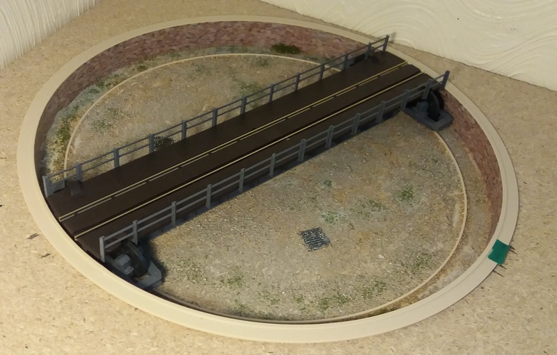
The PECO turntable had now been fully assembled (surprisingly easy to build - nice kit) and the base weathered and generally 'dirtied up' (a rather untidy bunch of workers in this yard!) and the Locomotech motor and indexation kit fitted - the motor was initially tested using a simple variable power supply rather than having the indexation add-on fitted - and it appears to work fine; not noisy and is smooth in running.
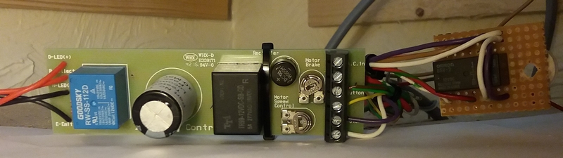
The motor indexation kit has since been fully implemented and setup and works extremely well. A couple of small changes from the initial paperwork have been made. The kit now states that a 16volt ac supply is required; also that a 12volt dc supply can be used. I found that the 12volt dc supply, together with a long cable run, failed to provide enough supply to run the motor when connected to the "ac in" connector. So I opted to make a direct connection to the smoothing capacitor, bypassing the bridge rectifier on the ac input (and it's inherent voltage drop). Also the motor drive has been passed via a changeover DPDT relay close to the main pcb (small add-on pcb to the right of the main pcb in the photo below); this gives a short cable length between the pcb and the motor - the relay then being controlled by a small SP c/o switch on the mimic board. Overall, this gives a much better (more central) setting for the motor speed control giving about 1 revolution/minute. The relay used here is an Omron G5V-2 12v with the 12v switching supply taken from the pcb ("button" output, brown wire in the photo - the yellow and green wires feed the motor "start" button).
The only one criticism I have of the motor indexation kit would be the (short) length of the cables to the index sensors which can restrict the positioning of the control pcb - but then again, it does avoid having lengths of cable to tidy away if the pcb is located close to the turntable. I guess there's no reason why I couldn't extend the cables myself so I can locate the pcb in a more convenient place. Will have to give that some thought.
The well sides have been 'bricked' with a London Multi Buff brickwork print and the well itself well splattered about with sand, a light covering of a matt grey paint and some 'greenery' to add some effect of being left largely untended. There is still plenty of work to do on the turntable - such as painting up the guard rails and stanchions, adding some rust to the rail sides and to add some brickwork to the circumference of the upper well. That's all for another day. In the meantime, I've some trackwork to start fitting….
A few short lengths of track have been fitted in the hidden section and a couple of IrRd sensors have been fitted to this trackwork under the Terminus approach. The general construction idea is shown below (yet to be electrically connected). For the eagle eyed, the dark sensor is covering track to the left while the other (clear) sensor is covering track to the right - the matching 'other halves' of the pairs are not shown. Some circuit detail will be shown next time around (hopefully).
That's it for now - time for other household duties.
Posted

Full Member
Posted
Full Member
Two types of sensor are being implemented: one being the normal across-the-track type to detect where a train is located; this is within the hidden section so that if there should be an incident and the train stops, I'll have a good idea where within the enclosed space the trapped train is; the second type of sensor will be buried in the track itself and will be used for the automatic signalling as a train passes a signal (or a given point where no signal exists but maybe ought to, as in the hidden area). This is in preference to using a timer to change a previous signal.
The first type of sensor is a straight forward system that will light LEDs on the mimic board, nothing more. They are separate transmitter and receiver InfraRed pairs (of unknown type from the far east) - set at about 45degrees or so across the track; these drive into LM339 comparators to get a nice clean output for the mimic LEDs. It also allows for stray infrared light from other emitters and any natural light coming in. The circuit has been taken from a Rob Paisley design. I'm not sure that I can publish the circuit here (the diagram indicates it is copyrighted), but a search of the web (http://home.cogeco.ca/~rpaisley4/CircuitIndex.html) will soon bring it up (and many other interesting circuit ideas), both in single and quad formation - the quad design is being used here. Minor changes have been made, mainly around the comparator inputs (using a preset resistor) to offset any stray light that might affect the sensors.
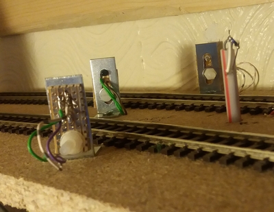
The sensors fitted, setup and working.
The LED/sensor holders are made from small angle brackets with a small piece of stripboard secured to it. Where space is tight between adjacent tracks the LED/sensors are fitted into drinking straws (!) with the wires taken back down the straw. It appears there is no need to paint the back of the receivers with a black paint to prevent light from other LED emitters giving false outputs (the setting of the comparator voltage offsets this sort of thing).
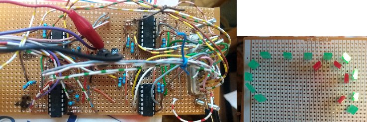
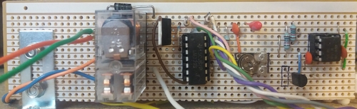
Hidden sensor pcb showing 4 LM339s (with a 25-way D-type plug with the inputs at the right) - and - the finished mimic indicator pcb.
As can be seen on the above photo, a train is residing towards the right, close to the exit from the hidden section prior to climbing up towards the Terminus.
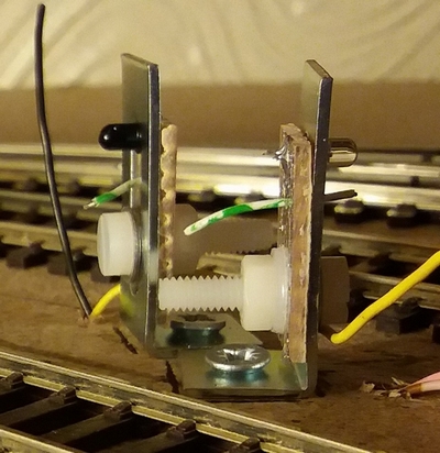
Basic testing on the under-track sensors for signal switching has been carried out and uses an RPR-220 InfraRed transmitter and receiver in one package that fits just nicely between two rail sleepers and is buried at around the same level, soldered to a piece of stripboard and screwed to the underside of the baseboard.

RPR-220 circuit board (small and nifty!).
The automatic signalling system will (hopefully) be using a large PICAXE chip (40X2) for the terminus departure signalling (maybe I'll need to use two chips - not enough input/output pins on one chip) and the remainder of the layout will probably be run by another 40X2; all these devices use 5 volts across the board, therefore the RPR-220 sensor pairs - or at least their outputs - have to run on that voltage. The LED/sensor circuit is much the same as that used above but, being used on a 5volt system here. There is still some discussion going on in my mind as to whether I'll run these through more LM339s before passing the outputs to the PICAXE chip(s). The LM339 will happily run on 5 volts (suitable for the PC chips) so that will be fine. The software still needs to be written, but the mind is turning it over in the background.
Maybe I should use 5 volts across all the sensors but the hidden section occupancy detectors using the LM339 circuitry running at 12 volts is more historic than anything else having been used on the previous layout. I will, however, be sticking with 12 volts as the LED wiring is now is situ and is configured in a four-LED chain which requires the 12 volts - and it's only used for mimic board LEDs.
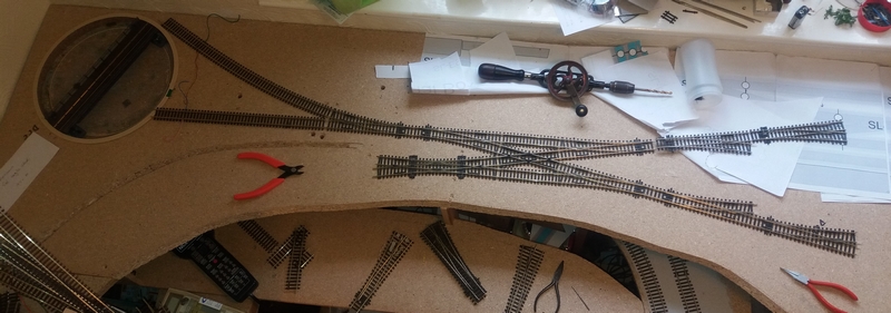
Finally, work on the Terminus approaches gets under way with the hidden section poking its nose out at the lower right!
The upper (Terminus) part of the layout has been started, as can be seen (above) - the pointwork is currently going in; the turntable has been placed (temporarily) in situ to get the impression of how it all lines up and how close to the AnyRail plans it is - so far it looks pretty close (the lengths of track leading to the turntable and that for the head shunt have been fixed at the turnout but need to be aligned to the turntable and cut to an appropriate length before final fixing).
Right. Back to work and fixing a few more bits of Terminus. Further updates to follow as and when.
Posted
Site staff
Ed
Posted
Full Member
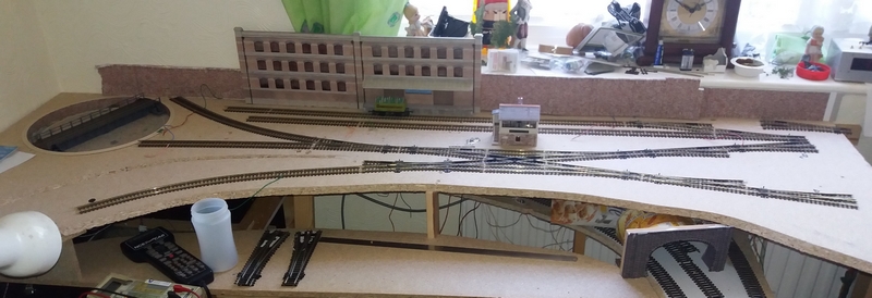
The buildings, walls at the rear and the signal box have just been placed on the baseboard to get a feel of things; the signal box location is probably about right - the other kits locations remain to be seen - the factory unit will be along there somewhere (the walls will probably be taken out and replaced with some more factory/unit buildings). P.S. don't look at the window cill - a bit of a dumping ground that never seems to get tidied up! We all have a "dumping ground", usually not on camera though.
The tunnel entrance, bottom right, is a hang-over from the old layout (again, just to get a look-feel of it) and needs to be thrown away and a fresh entrance built to allow three tracks to emerge from the hidden section.
Droppers still need to be fitted, despite the array of wires hanging down at the back of the hidden section.
Back again when there's more to report.
Posted

Full Member
cheers
Marty
Posted
Full Member
Other than that, the turnout motors - and their associated polarity switches and a mass of wires - for the terminus approach area - have now been fitted and freshly wired back to the yet-to-be-built mimic/control board. One turnout motor on the hidden section has had to be, how shall we say it, botched - or rather, re-botched. On the old layout it had been modified by shortening its activation pin to enable it to be fitted above the baseboard, this was due to constructional timbers underneath the baseboard at that time, and a lack of space above the solenoid within its "building" for the pin to be left in situ. So it will now sit in the hidden section together with a shorter activation lever to throw the frog.
The DCC feed wires have also been added here (on the terminus level) and also onto the entire hidden section of track where previously (for testing purposes) only one (central-ish) connection had been provided. Surprisingly, it worked pretty well given the connectivity around the track was simply reliant upon the fishplates. No doubt they would have given problems of poor connectivity (and running) given time. So this length of track needs DCC more widely applied.
But I've never seen so many wires in such a small area - colours of (almost) every thought going hither and thither. But it's all being documented and tidied up and is starting to look much, much tidier.
What else has been done? Not much, other than the investigation of various ways (I'm getting way ahead of myself here) of providing scenery and such-like. There's some very good instructional videos and articles out there. All I need before that is a completed and joined-up track layout - about 14m of track still to be fitted - together with some wire netting, modroc bandaging, a bit more plaster and some paint and then I can get on with this aspect.
I'm also looking around for ideas of how to motorise a pair of level crossing gates, such as the Wills SS56 kit. I've seen a few ideas, but most seem to make use of the Arduino board; something I'd prefer not to do. I think I shall have to look more into using cheap servo motors and some method of driving them at a reasonable speed. The spec of these motors show such a rapid move over 60deg (approx 0.12sec @ 4.8v) and there's very little documentation, or practical method, of how to slow the things down. Looking at the programming of the PICAXE chips, there seems a way of doing this by making the 90deg turn of each gate in small increments rather than telling to motor go straight from 0 to 90deg., and if necessary, adding short pauses between each increment. I've yet to give this a try. I seem to spend more time hunting the web than I do building the layout!
That's it for this update. By the next report I hope to have the run-around in place, the remainder of the trackwork installed and the DCC wiring fully fitted throughout as well as some sensors for the signalling. Then I can look into starting on the terminus area itself - oh, and the hidden sidings and the mimic board and the associated electronics.
Not much more to do. It'll be finished by Christmas - 2020! How's that for positive thinking?
Posted
Full Member
I'm pretty sure that I've seen servo motors used for level crossing gates successfully before somewhere. I'm sure you could find an example out there on the web if you look…. oh wait… I'm not helping am I ? hehehe.
I too found that the wiring underneath my baseboard seems to breed. Something to do with polarity frogs and relays and LED indicators on the mimic panel, let alone the switches themselves. But there is a certain level of satisfaction when it all works!
keep it coming
cheers
Marty
Posted

Inactive Member
https://www.youtube.com/v/hmYsWfxiHTk
Max
Port Elderley
Port Elderley
Posted
Full Member
And yes, I've seen servos used for many aspects of the hobby - very nice implementation on the roller blinds Max, nice one!
But my problem is, despite searching around the web for more hours than I care to consider, there appears to be little information around as to the "how to" control the speed of the servo movement. I appreciate there are a number of pre-built commercial units out there but I'm into self build if at all possible - and that's where information appears to be lacking. There's quite a few comments about such as jitter but very little on the reality of doing the job to start with.
Anyway, I've been and ordered some servos yesterday evening from the far east so, even though I'm nowhere near doing anything with them, I can at least, when they do arrive in a few weeks or so time, have a dabble with the PICAXE chips and software fiddling - unless I can find some other method of driving them at a reasonably slow speed - maybe not quite as slow as the roller blinds (impressively smooth from what I can see).
In the meantime, there's still plenty to be getting on with.
Posted
Inactive Member
There is a YouTube video explaining the process of controlling the servos, but of course I can't find it.

The main thing to keep in mind is that their relaxed position is in the middle, rather than at each end of their throw.
I'll keep looking. :shock:
Max
Port Elderley
Port Elderley
Posted
Full Member
Posted
Full Member
The photo above doesn't really do justice to the amount of work that has gone into getting to this point - but I feel it's worth a quick snap of it.
On the Terminus approach board there's more wires than BT has in one of their exchanges! Wires that will control the turnouts, wires that will carry turnout positioning signals back to the (yet to be built) mimic board, wires that carry the DCC power and wires that carry the +5volt supplies. I think there will even need to be a +12volt supply to be run yet.
But at last I can run trains into the Terminus approaches from a point close to the exit from the same point (the yet to be fully connected DOWN line). It's almost a complete end-to-end layout now (as planned). The Terminus itself has yet to be installed though - there's no baseboard in place for it yet; that still resides in the garage leaning up against the masses of other unrelated junk in there. Likewise, the hidden sidings baseboard is still out there waiting its arrival into "The Train Room". I really must get on with those remaining parts of the layout. Time is always a factor. Who said retirement meant plenty of times for walking the dog, hobbies, etc.? And we've no dog - although some pressure is being put upon us to get one.
Anyway, I've not exactly been idle these passed few weeks since my last post. Other than trackwork, various sensors have been added - both across the track (for location purposes in the hidden sections - see my post no.29 above) and under the track types (for different purposes) such as spot monitoring for the electronics such as signalling and the reversing section polarity changeover.
The latter being one sensor to sense when a train is fully into the section to have its polarity changed and another sensor to detect when it has left the section so that its power polarity can be reverted back to that at the start. I'm making use of RPR-220 diode/photo transistor pairs feeding into an LM339 then into a 555 bistable flip-flop driving a changeover relay. That's the theory; I'll let you know how - or even if - it works - I see no reason why it won't (but I'm no electronics expert - just a well-meaning meddler in the topic!).

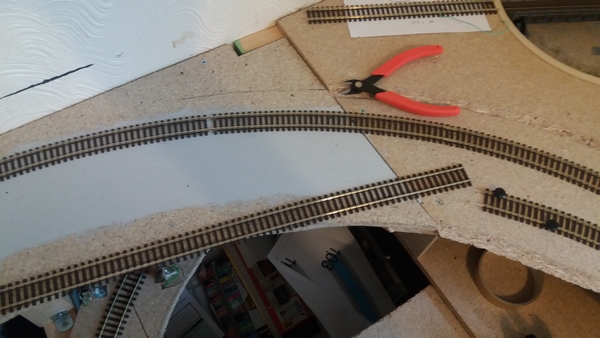
The above photo shows the climb (centre track) towards the terminus (with the Class 33 on the UP line while the Black 5 heads back on the DOWN line). The third line, far left, is an added passing loop with, what will be, a length of disused track (to become all rusty and overgrown) at the far end with the turnout long since removed.
Incidentally, the servo motors arrived last week and, like a load of other stuff I've ordered, they've been stuffed into a box in the cupboard. Something to be worked on a little later in time. I've been doing a bit more research into the subject and think I may have it nailed (and documented on disk so I've less chance of losing it).
That's it for this ramble; more in a few weeks when there's more to report. Cheers for now.
Dave
Posted
Full Member
Not long since the last post but some worthwhile success has been achieved that now allows me to run trains from on the Terminus Approach itself, round the layout and back onto the Terminus Approach. And then run them around again!
The Reverse Section circuit board has been completed, tested and installed:
Only a couple of minor changes since the photo was taken - a small LED indicator has been added at the lower right of the board to give me a visible indication of when the "section" has been switched over together with an open-ended wire that will connect to the signalling circuits to prevent an OFF signal when the reverse section is in the wrong polarity (this stuff will come later). The other change has been an adjustment made to the small preset resistor so that the switching point (in the comparator chip) is sensitive enough for the small piece of tin foil placed under each loco that causes the whole thing to trip over and then back again when the second sensor is passed over and not react to daylight or light from the room light.
Very pleased at this achievement.
Now I can make a start on the missing sections of baseboard and trackwork - namely, the hidden sidings and the Terminus itself. After connecting up the Turntable, that is; it's in situ - all it needs is connecting to power and the selector switch and also the track leading to it from the Terminus and the track into the small engine shed and aligning them to the stopping points.
That's it for now.
Cheers
Dave
1 guest and 0 members have just viewed this.