John Street - BR(E) - 1960
Posted
#219717
(In Topic #11972)

Full Member
My second bash at model railway-ing
At the moment this is essentially a placeholder for my new blog, about "John Street" - my new layout being built in OO gauge. At the moment there's nothing to see of anything other than my first layout, Langley Junction, which is still in place and still in working order: http://yourmodelrailway.net/view_topic.php?id=12834&forum_id=21&page=1For that layout there was little or no planning and it progressed in a bit of a mish-mash to the extend I could go no further with it. It also formed nothing much more than a twin-track circle. This layout - John Street - is an out-and-back scheme set on three levels.
It's there on paper and in my mind. I'm trying to do much more planning on it before making a start. In fact, nothing much will happen in the "train room" until later into the autumn when I'm not tempted to be out and about and can give more time to it.
So far, as I say, it's planned out on paper - designed using AnyRail software and I shall be making use of as much of the old kit as I can but, inevitably, more expense will, no doubt, prevail.
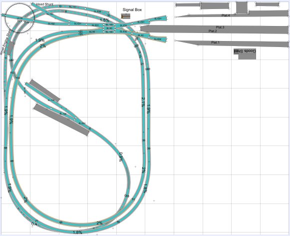
The white area is a no-go area; so I've had to make use of what I space I can while maintaining reasonablly sized curves. This is the main Base Level with the bottom of the reverse loop tracking under the two main lines that run up a level to the 4-platform plus two goods line terminus station at the top - not shown on here as I ran out of track pieces (evaluation copy only restrictions!) and a lower level hidden sidings area under the terminus also not shown for the same reason.
The turntable (Peco) has been bought (top left) and a couple of Scalescenes kits downloaded for the platforms and the small mid-track station. I've also been gathering a few parts ready for making the turntable up and, I hope, be in a position to motorise it and control it remotely. Also, parts have been got together for the Home signal at the terminus approach and I hope to make up a theatre indicator box to show which platform the train will head into. The chips are here for that and I've been getting a program ready to (hopefully) make it work.
The controls for these, and other items, will be run using PICAXE chips. Simple to program (using a form of BASIC) and are relatively cheap. I wondered about the Arduino Uno but there didn't seem to be much advantage - from a ports point of view at least - between that at around £20 and a PICAXE chip at £2.40. The both have to be programmed (the Uno in C++) and both appear to do a similar job (for what I'm wanting to use them for).
So anyway, that's where things stand at the moment. There will be more updates as time progresses and I start to make some progress towards getting John Street started and up and running.

Posted
Full Member
Terry
Posted
Full Member
One day…..! Soon, I expect.
But I've not been idle. There's been planning going on.
I've been progressing the electrical side of things. The signals program has been prepared for the exit to the terminus station - and if it all goes according to the script, it should all work nicely with the theatre box on the approach showing which platform will be accessed. The theatre display is a small 7-segment display in white (digit size 8mm high) driven from a 4511 BCD chip driven from a PICAXE chip. The only downside of the display is the physical size - slightly oversized (but there's not much I can do about that unless I have the display in, possibly, red - but not in white. Also, as is normal with all these displays, they are on a slant (italicised). But, other than that, it should look ok. The display has been delivered and should be ok for what I need. That will get built up into a sutable enclosure in the next week or so. I'm not into making up a small display box with the required number of fibre strands and lighting them that way - far too complex for my tired brain!
The other signals around the layout are in the process of being programmed. Again, the use of a PICAXE chip or two, will do the job of sequencing them all. Why use banks of individual transistors when one/two chips can do the job without the hassle of biasing each transistor and then linking them together, etc. The chips can drive an LED directly but when all outputs are driven 'on' at the same time and more than one LED is required from an output, then the overall power handling of the chip can easily be exceeded. With that in mind, the outputs for the LEDs will be buffered using ULN2003a darlington driver chips - just to get sufficient power to drive the LEDs on the layout and mimic board (and anything else that might need to get added on). Again, less fiddly than individual transistors. The theory is there, but the practicality may be a different matter.
I've also been trying to pre-document anything and everything related to the new layout - research is hopefully key to it's success during and post building. After Langley Junction, I found I had notes here, there and everywhere, both on disc and in written form - and finding anything specific was fraught with hours of hunting. That I am trying to prevent this time around. Everything is going into one folder on the disc and a Word document compiled with the directly important stuff put in it. To date it's up to 22 pages! And growing - rapidly.
The gradient will have a run of around 6m to raise the track up by around 110mm - according to a spreadsheet I found somewhere, that comes in at 1.8%. I guess that's largely do-able given that there is a 610mm radius 180degree turn along the way.
There's quite a long shopping list being collated - a lot of it will be coming from the Far East - including plenty of infra red emitters and receivers and the op amp/comparators for the hidden section (definitely a need to know where anything is at any given time), miniature LEDs of various colours for the mimic board as well as some homebrew Ground Position Signals, the 4511 BCD and ULN2003a chips, as well as sockets for them and some 5v regulators for it all.
Plenty of stuff coming along - will definitely need to make a start on the layout pretty soon. Basically, I can't really face breaking up a working layout. Clearing the floor space will be a first move. Empty boxes anyone?
More as and when….
Cheers for now.
Posted

Site staff

Think the hardest bit will be dismantling the current layout.
Good luck anyway :thumbs
Ed
Posted

Full Member
My eyes are still crossed from following the track around the 3 levels. Certainly maximizes the space. Looks familiar - Stan Jenkins used something like this for a 2-level Witney/Brampton/Fairford back in 1976. Cyril Freezer in origin no doubt.
That's looks like a 40' run around the upper, middle and lower levels (I'm assuming a 1' grid, or is it metric and meters?). Any reason for the fluctuating gradients?
Are those areas in the loops accessible? (Can you stand in them? Long arms otherwise, especially if that is a meter grid
 ).
). I did a quick calculation (in the head and counting squares so not that reliable): You have a ruling gradient of around 2%, which is 1:50. The run of the down from the main terminus to the top section of the track (under the signal box and turntable) is also around 40 feet for the lowest level. Which is going to give you a vertical distance of 12" between the top and bottom levels. Significantly less under the turntable if motorized. Throw in the baseboard frame and that could be around 9" or less as you have 2 levels underneath. If the top 2 feet are covered with an upper level baseboard you could have accessibility issues. Your metric calculation gives I think 4.33" (110mm) per loop with a run of 6m (19.5'), so 8.66" twixt top and bottom and a total run of 39'. Bit tighter than I calculated if the average gradient is 1.8%.
Could the turntable be moved to the lower loop to make a small motive power set-up with the shed ? If A1 is the top LHC, with letters horizontal, numbers vertical, this would be B6/B7. Not the first time a turntable and shed was a few miles away from the station.
Put a carriage shed where the turntable is, and have a station pilot shoving the coaches around. Three 60' carriages would probably be the maximum even on the long platforms if you have an engine runaround arrangement in the terminus.
The bottom LHC is intriguing me with the lowest and middle levels running on top of each other. Welsh valleys!
Nigel
©Nigel C. Phillips
Posted
Full Member
Ed, the PICAXE chips are small microprocessors - essentially they are the more standard PIC chips with a bootstrap on them so that no special hardware is needed to program them (at least, that's how I understand the description of them). Programming is done in (a form of) BASIC using the PICAXE Editor software. It's more for educational uses and to teach kids about programming - but they seem to have caught on with hobbyists. Makes life relatively easy and far cheaper - but probably less functional - than the Arduino Uno boards which have many, many add-on boards for various uses not needed here.
Anyway, that's what I'm hoping to use - certainly they're basic (sorry for the pun) enough for my needs. It's the "getting round to" the dismantling that will be the hardest part. Once I make the start, the rest will follow!
Nigel, the layout is in 1ft squares - yes, I'm still 'imperial', I understand it easier - never gone for the metric stuff! And yet I put metric measurements in my description. Guess I'm just a bit mixed up. But I've worked it through using imperial. Around a 19ft run from under the station approach (at +10mm above datum) to the double slip at the approach with a climb of around 4 1/2inches. The entire upper level from the platforms to the d/slip to the turntable is all on the level (at +120mm above datum). I'm not entirely sure where the datum mark is - somewhere under the turntable. Nothing, except the station, the small station halt on the reverse loop and the hidden sidings are on a level plane; everything else is either rising for falling. The lowest is -19mm and the highest +120mm. Apologies for any confusion in the size of the squares (imperial) and my measurements (metric).
The turntable will, I hope, have a small unipolar motor, 28BYJ-48 and a ULN2003a chip to drive it, so it is quite low profile, not like the Locomotech motor which is huge in comparison. The motor is already in the 'ready for installation' box - even I was suprised at how small the motor is. If the motor doesn't have enough "pull" (torque) I've seen an article on how to convert the motor to bipolar with a need to change the driver chip for an L293D; that'll give it more torque.
And yes, it is kind-of based on Cyril Freezer's Fore Street layout, very much cut-down due to the space available. The centre block is cut out for access to the "A" column along the back wall but is dissected by the reverse loop. "A" to "J" is horizontal and "1" to "8" is vertical starting top LHC (turntable) as you thought.
The bottom LHC is a bit tight - more so around D7/D8 - with the two (visible) tracks to the upper station having risen to +55mm at the point where the reverse loop goes under at -15mm. The 2 rising tracks, mainly the outer track, continues to rise well above the lower hidden loop. It'll be interesting to see if it works out, but I have every faith. I can't tell how many times I've looked at it and so long as I have the clearance for the necessary 60mm above track-top level plus the track itself and some (well supported) thin-ish base board, I should be ok. If it's still a bit tight, I'll have to drop the lower end of the reverse loop a bit more. It's all a bit flexible on how it'll fit together, but I don't think I'll be too far out.
Right, back to the drawing board.
Cheers for now.
Dave
Posted
Full Member
I'm quite used to mixing imperial and ISU/metric (I lived in Canada for 35 years, officially metric, worked in ISU for all that time, and bought lumber in inches and feet
). Those hidden sidings (A1-A4?) could be a bit tight to get at if something derails. The double slip is a great idea - significant reduction in real estate compared to a double cross-over or 2 single cross-overs.The specs for the stepper motor give around 15 rpm at 5v (no load) with a 1:64 reduction ratio. I presume the software would slow things down a bit. That little motor has quite large steps according to the specs (32 or 64 depending on the wiring, 11.25° or 5.625°) and may noticeably judder its way around at slower speeds, say 3 rpm (10 seconds for a half-turn). Can you regulate that with the software? I've seen stepper motors with 0.9°-1.8°. Could be a balance between steps/speed and torque. Not a subject I know a lot about, but all stepper motors I've seen in action driving turntables judder their around noticeably. Perhaps a much higher ratio? As with most things, I suspect little judder comes with a (bigger) price and a larger motor.
I filmed the real thing at the Didcot GWR site a couple of years ago - took the driver and fireman nearly 5 minutes to turn a Mogul (4-feet power). The balance was spot on, but that's a lot of mass to get (and keep) moving. Didn't help that in the excitement of the moment and an audience of around a 100 they built up too much momentum, overran the exit track and had to go back. We all yelled "keep on going!" Powered ones go at around 3 rpm unloaded, 1 rpm loaded - 30 seconds to turn a 100 ton locomotive. Too fast and the engine comes off.
Nigel
©Nigel C. Phillips
Posted
Full Member
All things electronic are getting more involved than I had first envisioned.
As mentioned earlier - and to expand on it - I'm using PICAXE chips to regulate and control the signals across the layout based upon turnout settings and next signal states. I was aware that these chips (along with the Uno) are restricted by way of the limited number of input/output pins. To overcome this to some degree, I have used the outputs to switch the Red and Green signal outputs on the same output pin. Ok, so far - this is well publicised by utilising the source/sink capabilities of the chips. This will limit the number of PICAXE chips needed (and saving some complexity in control signals between each of them), but at the same time involves additional logic. But as I am also likely to over-run the chips by taking too much overall current (by duplicating the signals onto the mimic panel) I'm not able to make direct use of this source/sink scheme. Therefore, enter the ULN2003a darlington driver - 7 i/o ports per chip - plenty of output current capability there.
But I still have the "1" signal level for one aspect (Green) and a "0" level for the other (Red). Now we need to add an inverter for those signals that have a "1" level (Green) coming from the PICAXE chips, namely, 5v ("1") into the inverter (74LS04) to give me a 0v (now a "0" level) to go into the darlington driver chip which, apart from current boosting, it also inverts it back to the "1" level, possibly 12v if the darlington is 12v supplied. The "0" level (Red) is also passed direct to the darlington to again give me a "1" to drive the other aspect. All is sweet and light again.
Now, this time around, we also have 3-aspect signals on the layout. A separate output on the PICAXE is OK for this and is also used via the darlington driver. To make the mimic panel show a yellow from a dual Red/Green LED, a simple matrix of 1N4148 diodes is used and should (I hope) work and give me a correct(-ish) colour. I've yet to try this out but I anticipate it should work. No reason it shouldn't - he says.
No doubt I'm reporting to those who have already been there, done that. But it's new to me and I'm still learning - even at my age, there's still plenty to try to ram into these tired old brain cells; whether it stays there is another matter! Bring in the ever increasing documentation.
More parts have been ordered and I expect them to arrive in a few weeks time. Then I can try to find the soldering iron from the bottom of the pile of junk and make a start.
In the meantime, back to the process of working through the software, collecting the necessary ideas and the parts needed and maybe even make a start on clearing the room and dismantling the old layout. Oh, I'd better document that!
One area I'm having some concerns over is the method of supporting the upper tracks over the hidden section (mainly down the left hand side of the layout, shown way above, and also across the bottom-left). I think I may have a solution - there's probably not enough room for conventional supports - so will need to give it some further thought. Watch this space.
Cheers for now.
Dave
Posted

Full Member
Posted
Full Member
Interesting approach to the electrickery and electoniks. I'm following with interest, sparked my curiosity enough to have a look at the system.
Nigel
©Nigel C. Phillips
Posted
Full Member
Many, many electrical parts have been ordered, mostly from the far east, and most have arrived safely (eventually!). The floor of the 'train room' has finally been cleared of so much accumulations of "junk" (boxes of this, piles of that) so much so I can now actually see the floor covering - so that's what colour the carpet is!!
I've been doing a lot of thinking, planning and Googling as to the best way forward to make the plans into reality, and how best to wire it all and how to lay the track and add the scenic bits, hills, etc. I want to install as much electronic stuff and add the wiring as I go as there won't be a lot of room to add it all once it the layout gets put together.
I do have one problem though. As this is a layout with no two sections of track on the same level as the next, quite what the best material to use for the base board for these rising and falling sections of trackwork and to provide a good transition between the two gradients needs to be considered. There seems to be so much differing and conflicting information out there. I guess it all comes down to personal preference in the end.
Do I use plywood? - 3mm seems very thin, 5.5mm 'might' do the job with a reasonable compromise on strength and flexibility, or 9mm ply which may be a little too stiff to allow a reasonable transition between any 'level' areas and the inclines. Checking the flexibility of a 6 inch wide strip from flexing an 8x4 sized board doesn't give you any real idea as to the suitability. 12mm chipboard would appear be too stiff (that's what I currently use on a 'flat layout'). Sundeala board seems, from reports, to be a bit too soft and wappy to be useful - maybe I'm wrong and it's fine to use. And I'm not keen on using MDF due to concerns over dust when being cut/drilled/etc.
On this point, I have a small dilemma.
My current thoughts are to use the 12mm chipboard for the level terminus, hidden sidings areas and the small halt station with a "base" board of the same material to provide the base which will support the rising/falling trackwork elements which will be sitting on (most likely) 9mm ply which will probably need to be supported every 6-9 inches or so to prevent sagging. Until I get the strips cut out I'm not sure how flexible the ply will end up - unless I can find a few off-cuts in the local DIY store to check it out.
All I need now is to work out the appropriate heights of each section of the main "base"board and to lower the height of the existing baseboard by around 3 - 4 inches.
Right. Back to the drawing board (and tidying the garden) and wait for the weather to worsen and I'm less likely to want to be outside.
Posted
Full Member
Decisions,decisions. With those multiple levels it might be worthwhile considering an open-frame design rather than a classical flat ply (or foam) top on which is then built the various levels. It would make putting all those electronic units in place a lot easier.
I know chipboard is cheap, but it has issues. I can recommend Baltic birch ply (after trying regular construction and veneered ply), it's a lot stronger (all those layers) and stable (minimal warping), is almost void-less, and has few if any of the overlaps beloved in the construction ply industry.
Nigel
©Nigel C. Phillips
Posted
Full Member
As time moves along I keep investigating for a methodology for making up the baseboard. I agree that using the 'flat earth' baseboard idea is probably largely a non starter and am looking at some form of open frame style of putting some of the layout together - certainly for the back section where the hidden track goes under the twin tracks to the terminus at the higher level. A similar arrangement will probably also be used under the terminus itself and, to a degree, along the opposite wall where the start of the hidden section ducks under the twin tracks. I know what I want to achieve but getting there is another matter. I also want to leave a fair expanse of flat baseboard to allow hills to reduce to a lower level such that I can develop some form of township or other lower level occupancy. So that has to be factored in along with the method of supporting the hidden section (also to allow access in case of de-railment, etc.) and upper trackwork overhead of it. I know I need to lower the height of the existing baseboard by around 3 inches leaving the rear part clear of surface board so that I can access the (lower) hidden track.
I've read reports on the various types and qualities of various form of plywood from various suppliers and have made a few searches. Marine ply sounds to be the best bet locally. Prices, at one (not of the big DIY chains) supplier, ranges from £26 for hardwood throughout ply, through to Birch BB ply at £44 and Marine ply at £50 (all + vat) - all for an 8x4 x9mm sheet. Locally at that store only the hardwood is currently in stock. Maybe a phone call will provide some form of expected (if at all) arrival of stock of the others. No great rush here, so will keep looking and a couple of phone calls may turn up something useful elsewhere.
Currently I'm doing a construction dummy run over a short distance with a few blocks of wood and some thin (scrap) ply - just to see how it pans out and how it will allow me to have the infra red sensors installed in the hidden section as well as the track feeds and, more importantly, to support the upper tracks above. And so it goes on.
I would have moved things on a little further today, but the weather remains good and I felt the need to go for an 8 mile hike along the local canal this afternoon. Tomorrow, the family is possibly visiting and on Sunday I'm off out with our local walking group trekking around the hills near Darley Dale, Derbyshire - that's an all day thing and is another day I'll not get anything done. But the mind is still active and thoughts will no doubt filter through for me to try. I seem to be able to do my best thinking when I'm not thinking too much about the subject in hand! Work that one out.
I shall get back into it again next week - unless anything else crops up and stops me. Monday is non too free, around miday-ish for a couple of hours, but the rest of the week is (at this time) clear; so here's hoping.
Dave
Posted
Full Member
After some months of not getting very far, very fast in the practical stakes - what with one thing and another as well as some illness just before Christmas, some work has finally come about with the beginning of the removal of the old trackwork from Langley Junction. Sad to see it go! The rolling stock and buildings were removed a couple of months ago. It's starting to look a little sparse now.
It's surprising what a rat's nest of wiring accumulated under the old layout, all thrown in with very little in any real thought about what it was for, where it ran or what interactions might arise. All the wires were documented - until I came to trace where certain wires went between the mimic panel and the end point - then it didn't appear to be quite so easy or straight forward! The spreadsheet seemed a good idea - and it worked until I came to think (and pre-document) ahead of myself and then it got mixed up somewhat. Never mind; it's all to be ripped out and the new trackwork and electrics will be generally far simpler, except perhaps around the terminus area.
A bit more thought will need to be put into it this time; keeping the small dc voltages needed for control purposes away from wires carrying the (momentary) higher solenoid power wires. Not such a problem on the new layout but will still need to be a consideration this time around.
Once the track is removed, the old baseboards will be taken down and a start made on building up the new multi-level baseboards.
A new year in a few days and a fresh new re-invigorated start. Watch this space - more updates to come once building work commences.
Posted
Full Member
There have been one or two changes to the (initial) overall design - nothing major, a few additional tracks up and around the Terminus station (for freight purposes) - the Terminus has not been shown before but had just included the four platforms with a couple of freight tracks parallel to the platforms and then leading through to the Turntable. The new tracks give a little additional scope for freight movements and now puts all the freight side of things on one side of the Terminus, whereas before it was spread to both sides of the Terminus itself (which probably would have looked a bit weird).
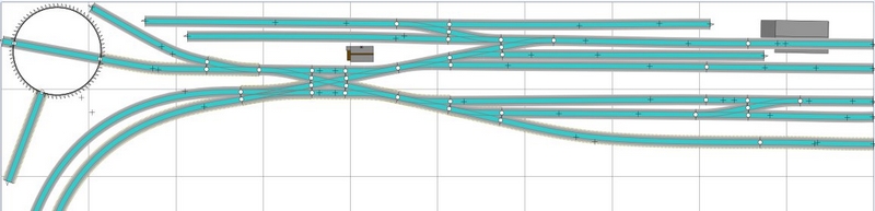
Also there has been a realignment of the little Halt Station, mainly to make landscaping a little easier. See the small inset sheet on the photo below compared to the same area on the initial layout at the top of this post. This also shows the hidden tracks under the Turntable, etc. to allow a reasonable 'run-around' in the small space available to me.
This lack of physical activity has given me the time to sit back and give the layout some thought and to make some changes here and there. I believe in the "6 P's" saying - Perfect Planning Prevents Pathetically Poor Performance.
I've laid out some printouts of the left-hand side of the Terminus and the approach tracks together with the Turntable (but not including the new additional freight area noted above) on an old (part) sheet of chipboard from the previous layout and which will be reused here and I've put on a couple of pieces of track to get an idea of what it will (hopefully) look like - and also some old bits of timber to give an idea of support and bracing; still a long way to go with this part of the job.

I'm not quite sure at which point to start building the layout - the upper level with the Terminus and Turntable? or start from the lowest point on the layout, just beyond the Halt Station? I had been thinking the latter, but am moving more towards the former now. The last layout was all on the flat so didn't present the same issues, i.e. it just got built. But this is all variable level trackwork and so requires different thoughts. Then there's the transportation problem of the new boards that are needed when I get round to visiting our local diy merchant - 8x4 sheets don't fit too well into the car! I'll get them in somehow.
Hopefully, I'll get back into the swing of things and be reporting more progress in the coming weeks…….
Dave
 Last edit: by Dave C
Posted
Full Member
But I've not been totally idle. I've now turned my thoughts to how I'm going to do the turnout switching mainly in and around the Terminus. On my Langley Junction layout I used a diode matrix to switch a number of turnouts together to select a route using the stud and pointer technique. But this was causing sparks at the point of contact with the stud and causing some interference to some of the logic circuity elsewhere on the layout. I guess this method is fine with only a single turnout being switched as the load was minimal; but I was switching four turnouts at a time and quite a hefty spark was being generated from a home made CDU fed from a 15v supply with a 4700uF reservoir capacitor - a pretty standard circuit.
I could use Darlington devices to do the switching with a much less driving current required through the switch than with the stud/CDU method to turn the device into saturation - and it's the current through the switch I am trying to minimise as much as anything else.
An alternative method of switching I've been looking into is using a momentary (ON)-OFF-(ON) switch feeding a low voltage at a low current into the usual diode matrix (for route setting) and then into a pair of MOSFETs to make the switch to one direction or the other. Either way, it's a lot of devices needed though (one for each pole of each solenoid). One minor problem here is how quickly the switch can be released thus stopping the current flow direct from the power supply and yet holding the switch long enough to enable the solenoid to successfully throw the turnout arms. Hold the switch too long and the solenoid could be damaged by the current flow through it. There's no protection in this method.
I came up with a straight forward, simple circuit for this but then just browsing the web (as one does) I came across a what appears to be, a more versatile and probably a safer circuit to make use of a fixed "pulse" width produced by an ON-ON (i.e. a normal c/o) switch to drive each MOSFET into conduction and at the same time providing a voltage to drive one or more LEDs (or other indicators) to indicate which track has been selected. What's more, it doesn't need a CDU as most other designs, although I would imagine, it would need a pretty powerful 12v supply (depending on the number of solenoids you need to switch at any one time). It looks to be an interesting circuit. See http://www3.sympatico.ca/kstapleton3/Index.html and http://www.classixaudio.com/pdf/751D.pdf for the circuit, etc. The only issue I have here is that the LEDs do not show the actual state of the turnouts, only what as been asked of the switch and the solenoids. Not a major issue as this part of the circuit can be removed and the more normal making use of the turnout switches themselves (if available) reflect the track selected. Or the two could even be combined using dual R/G LEDs - red for track selected and add the green aspect to produce a yellow to show action completed or to show a green if the turnout has been manually switched.
Before ordering a bunch of MOSFETs, I've managed to reclaim a device that might do the trick to do some testing before committing myself to the 751D design above. I'll probably make use of the power supply that currently supplies the CDU. That will give me a little overhead to make up for the loss of voltage across the diodes in the matrix. The MOSFET won't mind any additional voltage (rated to 60v on the device I've seen) and so long as the capacitors are rated accordingly, it should be fine. (he says hopefully!).
If only I had sufficient time to complete something already started. Being retired has given me less spare time than I ever had when I was in work - I'm not sure how that works, but there you have it in a nutshell. At least I'm never bored or just sat watching daytime tv to pass the time.
Posted

Full Member
Following along.
Marty
Posted
Full Member
Nothing too serious at this stage but, I feel, it shows there's a willingness there to put screwdriver to wood and wood to wall (well, there's plenty of time for that yet; let's not rush things!). But I have over recent weeks made printouts of the Terminus Station (John Street) and the approaches to it and, having (again) cleared a space on the floor, I've finally laid out the approach tracks over a piece of chipboard which, as I say, is currently residing in that recently cleared space on the floor. I'm none too keen on MDF due to the health hazards associated with the dust; but each to our own preferences. I think I've been here before with the printouts (see above) - but that was just a quick preview of things and since then more of a freight area has been added to the rear of the signal box as per the AnyRail diagram in a previous post. Now it's starting to get more serious.
I've also placed some more trackwork (together with old hookup wires in most cases) over the printouts to get more of a feel for what it should look like. There's still gaps where various parts have yet to be unpacked (or cut to length) but it now gives me more of an incentive to get back into the "train room" and get something done instead of sitting at the computer with ever more planning.
Most of the electrical bits have now been received and already in the box awaiting somewhere to fit them. All I need now is a few lengths of timber to support things and a few rawlplugs, brackets and screws and I'll start to get building.
More as and when progress gets somewhere. Don't hold your breath, it might still be a slow progression!
Posted
Full Member
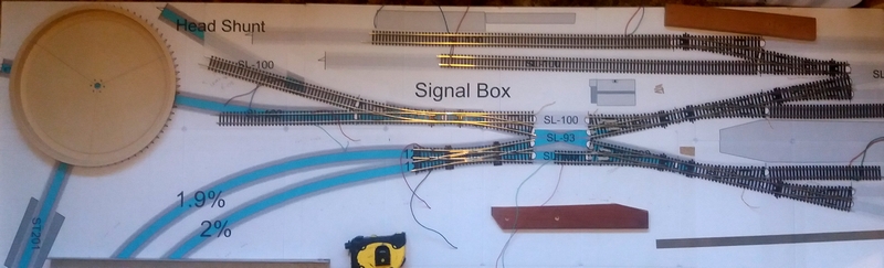
The basics of the board-work is being carried out; the approach to the terminus is in place - still not fully fixed in position as track, points, solenoids and sensors need to be fitted before that can happen. Most of the main boards though are now in place - a few still need to be measured up and slotted into various gaps. The start of the slope up to/from the terminus from under that same terminus at the hidden sidings turnout is now prepared and fitted. The remainder of the slope should be a relatively simple matter.
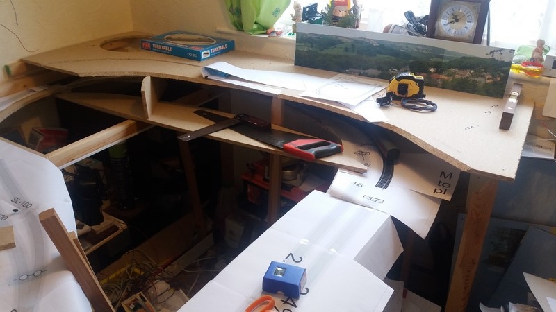
The above photo shows the approach to the terminus board (still to be extended into the terminus itself) with the hole cut for the turntable at the left side and the hidden section underneath (as yet the hidden sidings are also still to be added) - a loose bit of track and a coach can be spotted just to check clearances under the terminus.
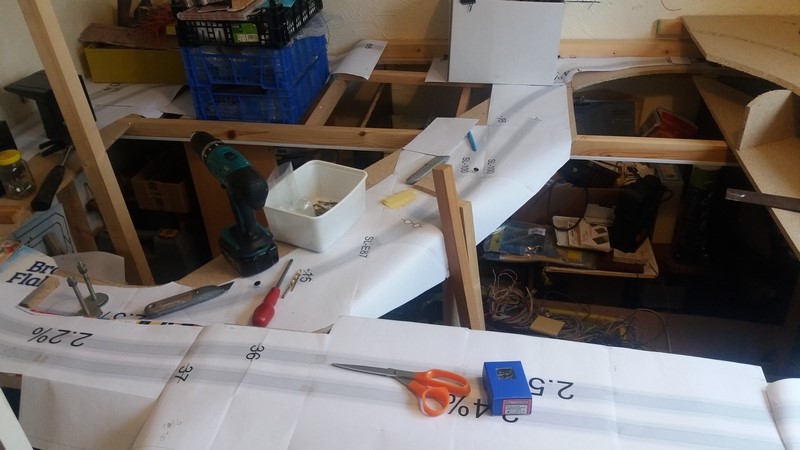
This photo shows what will be the reversing loop and where the halt station and short siding will be placed before the track drops down under the slope to the terminus at the left of the photo. Apologies for the Bran Flakes box in the left of the photo! - being used as a template to cut the next piece of board with the tunnel entrance from the loop into the hidden section.
Still lots of work to do, but I can begin to see where it's all going and the planning appears to be working out. Seeing it on paper is a lot different from seeing it built. Once all the boardwork is in place, the track can be laid and some of the electronics can be added for sensors in the hidden area and signalling cables.
Posted

Full Member
I noticed on another thread that you asked about motorising the turntable.
I also noticed that you have very few entry / exit points from the turntable so a Locomotech motor without the indexing disk might do fine for you.
I fitted one to my Peco turntable & tested it using an old H & M DC controller. I found that with the quality of the Locomotech motor that I could run the turntable so slow that I could hardly see it move at all. Its very easy to line it up by eye.
I don't know whether you are DC or DCC but either way it should be no problem to use the Locomotech turntable motor.
It does require a bit of clearance under the baseboard but I could measure that for you if you need.
Regards.
Tony.
Last edit: by spurno
"The only stupid question is the one you don't ask"
Regards.
Tony.
Regards.
Tony.
1 guest and 0 members have just viewed this.