00 Gauge - Maxmill Junction
Posted

Full Member
Petermac's Railway
A good idea John - like this ?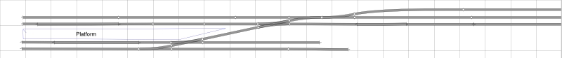
Incidentally, the squares are 6" - I still have to leave room for the Maxmill module at 6ft long plus a 180 degree return to pick up Maxmill Junction …………….:roll::roll::roll:
This section starts around 8ft from the left hand end of the room …………..
'Petermac

Posted

Full Member
Incidentally even at 6" there is still lots of room.
Posted

Full Member
Cheers Mike.
Free 00 Gauge Card kits can be found at
www.wordsworthmodelrailway.co.uk
www.wordsworthmodelrailway.co.uk
Posted
Full Member

I suppose it is a great loft for a layout although, as with most lofts, access isn't absolutely ideal - particularly if I want to shift 8 x 4 sheets of ply etc. ;-)
'Petermac
Posted
Full Member
The siding at the top will have to be kept free for coach shunting etc. and, for "town planning" purposes, the area at the bottom would be my preferred site bercaue I can "drop" the road level in the station yard to have coal "drops" rather than staithes.
The problem is, how do I get there with the wagons ?
Not a major problem with the drops - I could just pull them out of the station area and reverse over the drops.
The problem is the goods shed. Locomotives were not, for obvious reasons, permitted to enter a goods shed so the shunting loco would have to be at the left hand end of any wagons entering the shed. Without using 2 yard locos (a bit extravagant, even for Maxmill), how would I do this or, where else could I place the goods shed so the shunter is at the right end of the wagons ? ……………
 hmm
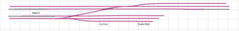
hmmThis is the revised station plan including the new siding:
'Petermac
Posted
Full Member

If I reversed that siding so it is entered from right to left rather than from left to right, and swapped the positions of the drops and the shed, all I'd need would be a long enough headshunt to clear the point leading to the siding ………….:roll::roll::roll:
'Petermac
Posted
Full Member
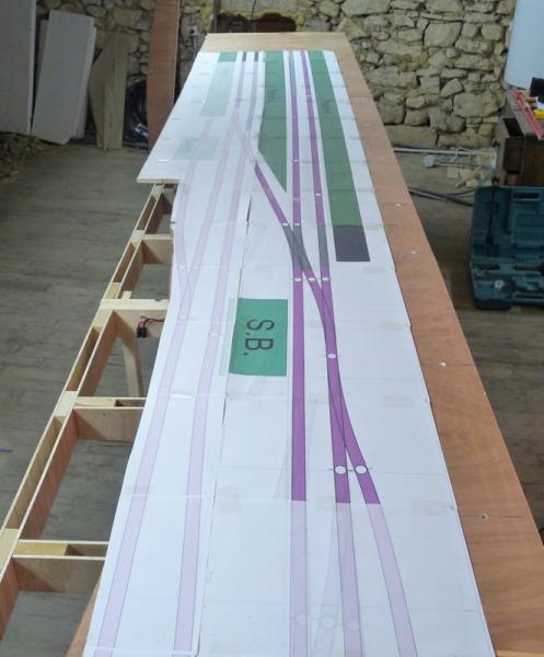
I laid out the "Anyrail" print of the town station to see how it looked. It surprised me just how big it is - the right hand platform is a tad shy of 6ft long. The green areas are the platforms which will be covered by a Scalescenes "large overall roof". "SB" is the signal box site although it's rather too big as shown. At left are the coal drops and goods shed with the station yard road leading out along the left hand board edge to the high street at the top:
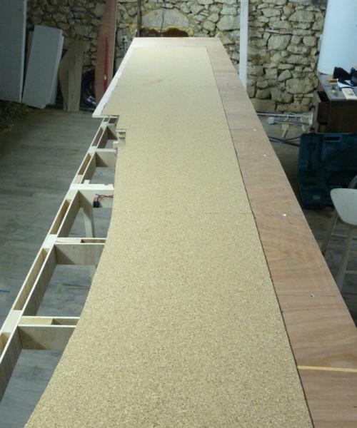
Being relatively satisfied with at least the platform areas, I covered the whole of the station area with 2mm cork. The platforms will sit on top of the cork to avoid any problems with differing levels. At the far end, there will be the main station building at right angles to the tracks with the "High Street" scene right at the end of the board. To the right, a road will lead towards the foreground and eventually to the Maxmill Engineering show module. Operating will be from the left hand side and the backscene board is still to be purchased and fitted:
I ought to mention that the baseboard surface is 10mm ply and is raised 15cms above the frames. Maxmill Town is a terminus at the end of a branch line from, but higher than, Maxmill Junction. The tracks will gradually descend towards the foreground to frame level, having passed through the old "Maxmill Engineering" show module, and join the main lines at Maxmill Junction. This lower level layout will be a complete circuit where I can watch the trains go by.
'Petermac
Posted
Full Member
Posted

Inactive Member
Tell us about the unclad part of the top. I must have missed the explanation in the text.
I would have thought that covering the entire framework would give it ultimate lateral stiffness.
Max
Port Elderley
Port Elderley
Posted

Full Member
Posted
Full Member
The uncovered part is so the scenics can drop below track level. It's where the coal drops will be. You can see the cut-out on the shot with the cork covering where the actual drop will be. The goods yard track will pass over this "hole" and on into the goods shed. Coal wagons will stop at the "hole" and either drop the side door or drop the bottom trapdoors, depending on the type of wagon. In the case of the trapdoors, the coal simply fell through the tracks into the bay below.
The yard road will drop from ground level into the coal yard where the surface is cut away at right angles. There will be a retaining wall along the edge of the coal yard with the tracks at high level.
The stiffness comes from cross-bracing on the legs Max. The "top" is screwed to small sction cross battens which in turn, are screwed to the risers. Sorry, I ought to have taken a photo ……..
 I'll do it on the next board.
 Dave, I can take no credit for the design of these baseboards. It's an idea developed by Barry Norman, a well known railway modeller and modelling author. I call it "girder frame" construction. It allows you to create scenic work both above and below track level.
You can read all about it here: http://yourmodelrailway.net/view_topic.php?id=4842&forum_id=5
It's quite a bit more work than conventional "open topped" baseboards but they claim to be stable and are lighter than using softwood size for size.
'Petermac
Posted
Inactive Member
Max
Port Elderley
Port Elderley
Posted
Full Member
'Petermac
Posted
Inactive Member
Max
Port Elderley
Port Elderley
Posted

Full Member
"The only stupid question is the one you don't ask"
Regards.
Tony.
Regards.
Tony.
Posted
Full Member
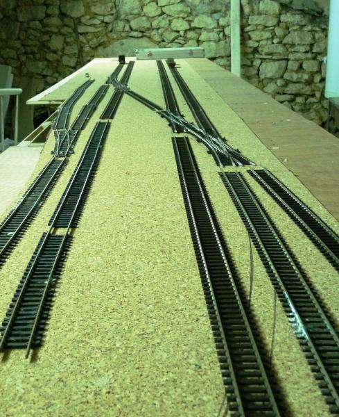
Having now got my 3 double slips, I thought I'd fit them in place. Ignore the gash trackage in the foreground and on the goods siding to the left - that's just some old stuff laid out so I could see what comes next ………:roll:
The idea is that the mainlines arrive on the 2nd and 3rd track from the right. All platforms can be accessed from these two tracks and stock cleared releasing the locos via the 3 double slips without blocking any on the mainlines. The main arrivals/departures platforms on the right are in excess of 6ft long to allow some decent length trains (providing they can make it up the gradient from "Maxmill Junction" which will be around 3" lower. :hmm)
Here's the pointwork in place for the station throat:
This higher level shot gives a better idea of how it all connects:

Tracks from the left: (excluding the short bit far left which I forgot to move !! :oops:)
1. Coal drops and good siding
2. Station pilot and siding to clear stock from left hand platforms to release loco.
3. Down Mainline
4 Up Mainline
5. Siding to clear stock from right hand platforms to release loco.
'Petermac
Posted
Inactive Member
Max
Port Elderley
Port Elderley
Posted
Full Member
Posted
Full Member
It was always intended to tack my Cornwall Show module onto the Town part of the layout and to incorporate "Chocolate Pudding Lane" into the lower level "Maxmill Junction" where there will be more flexibility.
Don't ask why, but I started with the "Town" station at the higher level …………:roll::roll: Probably because I couldn'tt get at the lower level because of all the junk …sorry, "carefully stored jems collected during our lives", that I have to share the attic with at present.
This is the current state of play: (Please excuse the "jems" lying around) ……..:oops::oops:
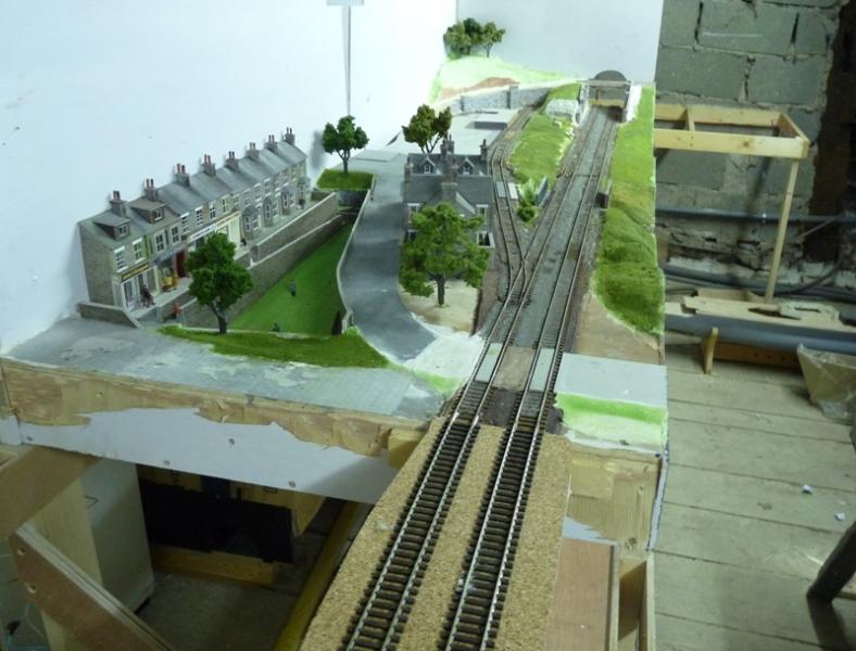
This shot from the end of the station throat looking towards the "Maxmill Engineering" module. The twin track will turn through 180 degrees to the right through the archway at the far end and descend towards where the photo was taken:

Looking back from the module towards the terminus "Maxmill Town" station:

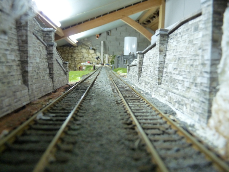
Driver's eye view as he exits the tunnel and enters the module:
"Maxmill Engineering" works is situated on the siding to the left. A small worker's commune was built on the outskirts of Maxmill to accomodate them:
The road leading to the works:

'Petermac
Posted
Full Member
Love the detail work in the embankment walls, that drivers eye view certain looks great to me.
Totally thumbs up work.:doublethumb
Cheers Mike.
Free 00 Gauge Card kits can be found at
www.wordsworthmodelrailway.co.uk
www.wordsworthmodelrailway.co.uk
1 guest and 0 members have just viewed this.