Monthly Project - February 2012
Posted
#133776
(In Topic #7106)

Legacy Member
Constructing Operational Signals.
Great project last month and I'm pretty sure we are going to get another one this month as I think I see a volunteer on the horizon.
Posted
Full Member
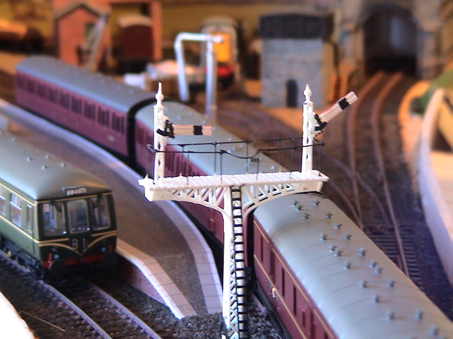
I have grown an interest in both semaphore and colour light signalling and propose that we try to cover both in this project. Scott (scott0020) is constructing a superb gantry for colour light signals in N, so I hope he will join in and show us more about how he is doing that.
The gantry which I have nearly finished has both semaphore and colour light signalling on it and although not common, I have found some prototype photos of similar arrangements.
I still have an unbuilt Ratio kit, so I propose that we start with that as I know the thought of soldering small brass parts is daunting for some - but it is not as bad as it looks when you try it.
I think that the addition of signals to any layout is a significant step to getting closer to a true model of the real thing, but clearly whether they are operational or not is very much up to the operator. I do like to see signals changing on exhibition layouts, and if there are several operators, it is an easy way of controlling train movement if the signals are observed.
I have controlled my semaphore signals so far with memory wire motors, but the way I have constructed the signals means that they could just as easily be operated by hand with wire in tube, or by any other mechanical means such as servos or relay armatures. I will try to illustrate this during the project.
As the final part of this introduction, I must make reference to two people whose guidance I have followed closely. Firstly Andrew Hartshorne of MSE. I have spoken to him at exhibitions and on the phone and found him very helpful and patient with my early "silly" questions. I find that his range of parts are well suited to my construction capabilities - they look very good to me, although I admit that there are more finer-scale products out there. The second is Mick Nicholson and in particular his book entitled Constructing and Operating Semaphore Signals. The book is full of very useful guidelines which I have found very helpful. As I have gone along, I have varied a few things, but I would whole heartedly recommend his book to anyone wanting to seriously take up the construction of semaphores. I have also corresponded with him on RMweb and again he was very helpful.
Posted
Full Member
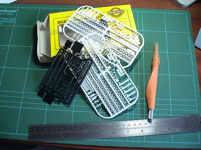
They pack plenty of parts into the supplied frets which give lots of different possibilities. I am going to build just a simple single home arm lattice post signal so I need these parts:-
To the right hand side is the post which will be made from the two white lattice pieces together with the square black base and the small white finial. The black ladder and safety hoop will be added as well.
Above the post parts are the arm parts. These comprise of the arm itself, a moulding of lamp and arm pivot, and the back blinder. I have opened up the holes in all of these parts to 0.5mm, which is what they had been moulded with, but were a little too tight. (The Ratio instructions do recommend running a drill through the holes). My pin vice is laying on top of the 0.45mm dia wire supplied in the kit, and we will use this for the arm pivot and the operating wires.
To the left of the arm parts is the balance lever which has had the two operating holes opened up to 0.5mm, but has had the pivot hole opened up to 0.8mm, as have the balance lever supports and the small black end plate. This allows the use of a 16BA bolt and nut to be used for the balance lever pivot. Something I recommend if the signal is to be operational. Although they are small parts, assembly is quite easy and leaves the parts moving freely.
 Last edit: by Geoff R
Posted
Full Member
I have not worried about painting for this exercise, but normally it might be best to paint the arm whilst still on the fret.
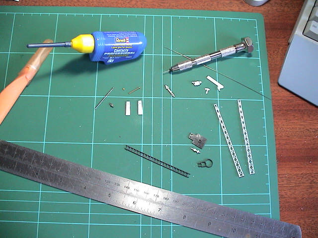
The key parts for us when considering making this operational are the arm pivot:-
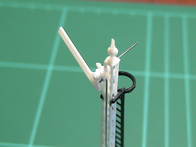
and the balance lever pivot:-
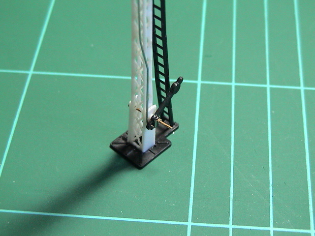
I have bent up a length of wire to fit through the operating lugs of the arm and the balance lever. It helps to tighten up the balance lever pivot nut on the 16BA bolt to hold things steady whilst fitting the wire. The next stage will be to add an operating wire through the base.
Posted
Full Member
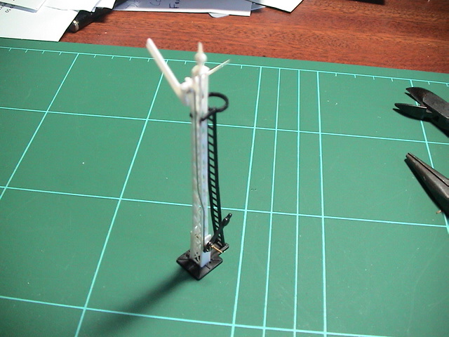
I have added a control rod and fixed it to the rear hole provided in the balance lever:-
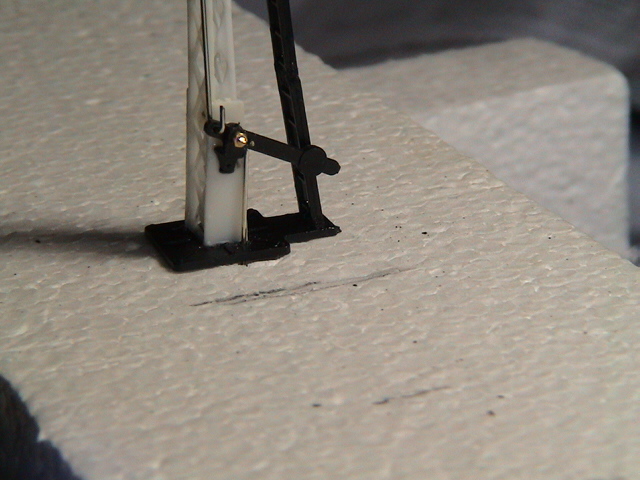
This then passes through the baseboard:-
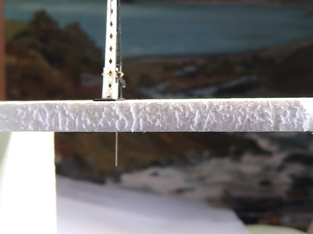
where it can be connected to a crank and then whatever control mechanism is preferred. If a weight is added to the bottom of the control rod, then a simple cam to push the rod up will clear the signal off, the weight returning it on.
If there are no questions or suggestions, I will move on to a single brass signal next.
Posted

Full Member
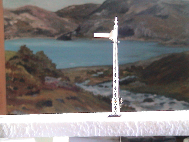
It was quick - started at 11.29am French time and finished by 7.53pm …………..:shock::shock: (or maybe it's a Blue Peter "here's one I made earlier" version …….
 )
)Do I take it this particular signal post only has 2 sides ? i.e. 2 lattices leaning up against each other. When I made one in black and white TV days, I thought they were made from 4 faces to make a tapering square block structure.
As you know, all my stuff has to come from UK and, as I'm over there at the end of the month, I'll make a shopping list and join you in this project a month late if that's OK ……………..:roll::roll::roll:
It will however, be Ratio kits this time around - brass is somethnig I've yet to learn to use. Hopefully, you're about to show me how. :cheers
I do agree that signals are one of the additions that "make" a layout. Without them, it's like engines with no crew or coaches with no passengers ……
'Petermac
Posted
Legacy Member
Posted
Full Member
I spent less than an hour on it during the day, Peter. It really doesn't take long to fix these parts together.It was quick - started at 11.29am French time and finished by 7.53pm …………..:shock::shock: (or maybe it's a Blue Peter "here's one I made earlier" version …….
The single post comprises of just two parts which have half of the side at right angles to them moulded on to them. When glued together they form a representation of a four sided lattice.Do I take it this particular signal post only has 2 sides ? i.e. 2 lattices leaning up against each other. When I made one in black and white TV days, I thought they were made from 4 faces to make a tapering square block structure.
They do provide four pieces for the base of a bracket signal like this one:-
It will however, be Ratio kits this time around - brass is somethnig I've yet to learn to use. Hopefully, you're about to show me how. :cheers
I will try!!
Posted

Full Member
I'll also be interested in learning how to use memory wire to operate the signal arms.
Stu
Stubby47's Bespoke Model Buildings
All photos I post are ©Stu Hilton, but are free for use by anyone.
Posted
Full Member
I've also looked in said Ratio box - my, aren't those bits small !!
Stubby47's Bespoke Model Buildings
All photos I post are ©Stu Hilton, but are free for use by anyone.
Posted
Full Member
Even allowing for my lack of skill, that could turn out to be my Achilles Heel Stu ………….:hmm…………………………………..
I've also looked in said Ratio box - my, aren't those bits small !!
'Petermac
Posted
Full Member
Suitable GWR signal now purchased, and a pack of 16BA fastners on the way from Eileen's Emporium.
I've also looked in said Ratio box - my, aren't those bits small !!
I have one of those magnifying glasses on a stand with little clips to hold things, and that helps sometimes, but my favourite way of at least seeing these small bits is this:-
 Yes, but it does work!! By the way, if you think the Ratio bits are small, wait until you see the 16BA nuts.
Posted
Full Member
Stubby47's Bespoke Model Buildings
All photos I post are ©Stu Hilton, but are free for use by anyone.
Posted
Full Member
I started with an all in one kit:-
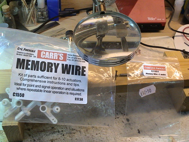
A great way to start as it includes everything you need. Also shown in the photo is a packet of memory wire - unfortunately I only have a few centimetres left at the moment, so you need to peer carefully into the plastic bag to see it.
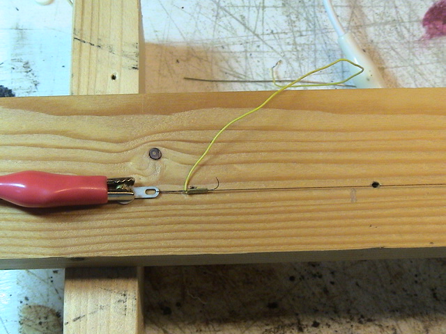
I then built a simple experimental rig:-

I used about 75 mm of memory wire and attached it via supplied tags and crimps to a fixed screw one end and a supplied spring the other end. The wire must be held in tension for it to work.
Here is a close up of the crimp and tag connection:-
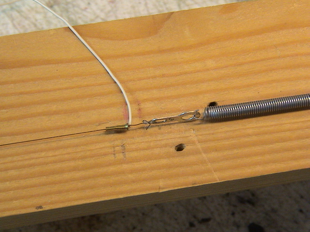
The amount of movement you get is proportional to the amount of current you pass through the wire. The shorter the wire, the lower its resistance. The 75 mm length can be connected directly to a 3v battery source and will draw around 350mA:-

I have drilled a small hole in the tag at the spring end, and marked its position on the piece of wood with a black pen line. Now when the battery is connected to both ends:-
you can see that the memory wire as contracted about 3mm as the black line is now in line with the larger hole in the tag.
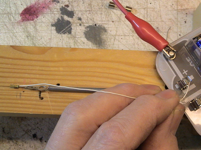
Whilst I showed above having the memory wire connected via feed wires crimped to its ends, I have learnt that a perfectly adequate connection can be had from the fixed screw …
and the spring:-
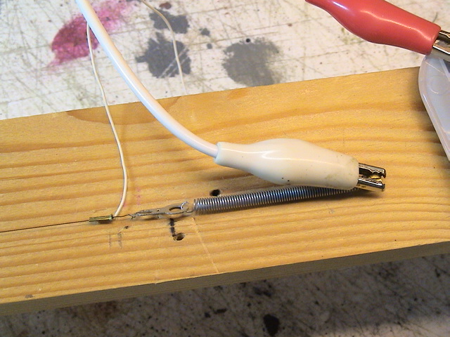
You will see how this is very useful later in the project.
So now we have a tag with a small hole in it that we can move about 3mm. We need to transfer this movement to our Ratio signal. If we mount the memory wire "motor" horizontally under the baseboard, we need a crank to transfer the movement from horizontal to vertical.
Again supplied in the kit, are some plastic cranks and pivots. I have started by fastening a pivot to a small piece of balsa:-

I then assemble the crank onto the pivot and attach it to the small hole in the tag at the spring end of the memory wire:-
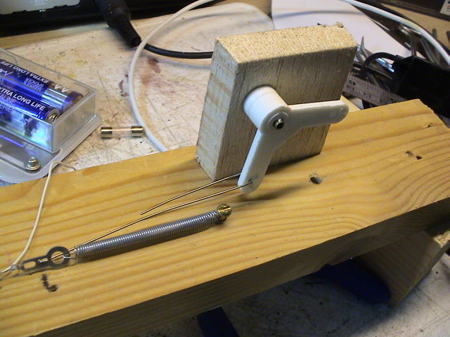
Now when we apply power to the memory wire:-

…the crank provides vertical movement of nearly 3mm. (A little is lost in taking up slack)
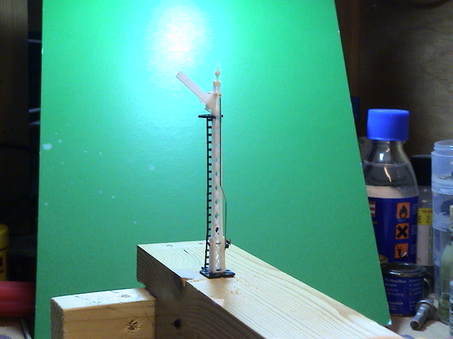
So now if we turn our "motor" up the other way, and mount the signal on the other side:-
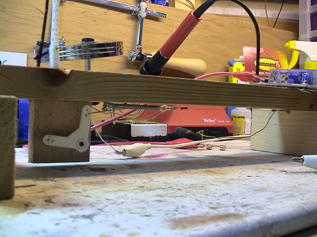
… and attach the control wire from the signal balance weight to the vertical side of the crank, we have an operational signal.
Firstly at rest:-
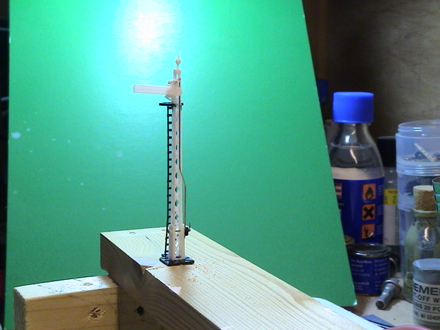
then operated:-
If you give it a try yourselves, please do post some pictures.
Last edit: by Geoff R
Posted

Full Member
Thats an outstanding tutorial.I bought one of these memory wire kits years ago for my "To do in the future box" & this is just what i was looking for. Recently a chap on another forum showed how I should signal my layout and I am in the process of gathering various Ratio signal kits for the job.
You used a 3 volt battery pack & i was wondering what would happen if you used more power ? I will have 9 volts Dc bus under the layout so I suppose I could use that with a resistor ?
"The only stupid question is the one you don't ask"
Regards.
Tony.
Regards.
Tony.
Posted
Full Member
The thing is though, that most of us don't have constant current supplies with our model railways, but we do have constant voltage supplies - such as 3volts of battery, or 12volts DC or even 9volts as you have.
The supplied kit includes a 5v regulator chip, but I never found much success with using that - you might find different.
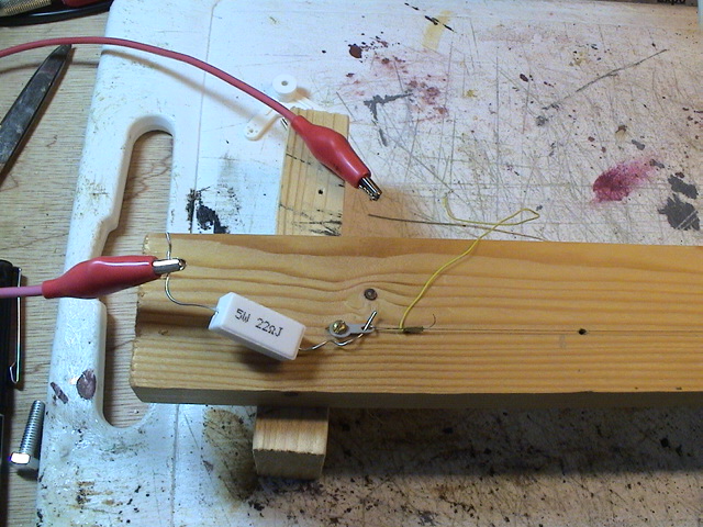
Some experimentation may be needed, but I have found that with around 75mm of memory wire, a current of about 400mA will flow if connected to a 12v DC supply through a 22 ohm resistor. The resistor will dissipate around 3.5 Watts while current flows, so it needs to be a beefy one like this:-
With 9volts, you would either need a smaller resistor or a shorter length of wire. I have found it is easier to stick with the 75mm length (around 3ins) and then find the right resistor value. I think that 15 ohms might be right for you. By my calculations, that would drop 6volts when 400mA was flowing, which would leave you with exactly 3v across the memory wire, from your 9v supply. The 3v of battery only allows 350mA through 75mm of wire, but just a little less current through your resistor will increase the voltage across the wire, and thus increase the current flowing, so it will settle out somewhere close, I think. I recommend testing with a multimeter in series if you have one, so that you can measure the actual current flowing.
Perhaps you could let us know how it goes?
Posted

Full Member
Frankly I am lost for words………..it as an absolutely superb tutorial……a model of clarity……I am sorely tempted to be diverted, yet again, to model at least one working signal on Granby.
There is literally nothing I can add other than to support Geoff's comment that any painting Arm, Finial (did the LNER have finials?), blinker arm etc is all done before assembly. I find it best to do them in batches so I have stock of ready painted arms. I imagine if the model is to be working one would have to be far more careful than I when painting and certainly drill out the holes after painting
I have always been tempted by MRE kits so I look forward to your next post
Posted
Full Member
Forgive my ignorance of electronics & the simple questions i might ask.You're using a 5W resistor but can it be higher 10watts etc
"The only stupid question is the one you don't ask"
Regards.
Tony.
Regards.
Tony.
Posted
Full Member
10Watt rated resistors will be absolutely fine. The rating is a maximum, so any power less than the amount the resistor can handle is fine. Be aware, that these ratings assume a level of cooling, so you cannot run a 5Watt resistor at 5Watts for long without some sort of heatsink. I make sure that just like on the prototype, the semaphore arms are only held in the off state with the memory wire energised, for a short period before the train arrives, and are set back to the on state immediately the train passes.
I should have calculated the resistor rating you would need running off 9 volts. Going back to my workings above, there would be about 6 volts dropped across the resistor with a little under 400mAmps flowing through it. That makes a power rating required of 2.4Watts. If you have 10Watt, 15 ohm resistors available, they will therefore work well. They will still feel warm when the memory wire is energised, as the 2.4Watts does nothing other than generate heat.
Posted
Full Member
When they arrive I will start my experiments.
Last edit: by amdaley
"The only stupid question is the one you don't ask"
Regards.
Tony.
Regards.
Tony.
1 guest and 0 members have just viewed this.