Track joining
Posted
#244070
(In Topic #13478)
Full Member
using peco track clips
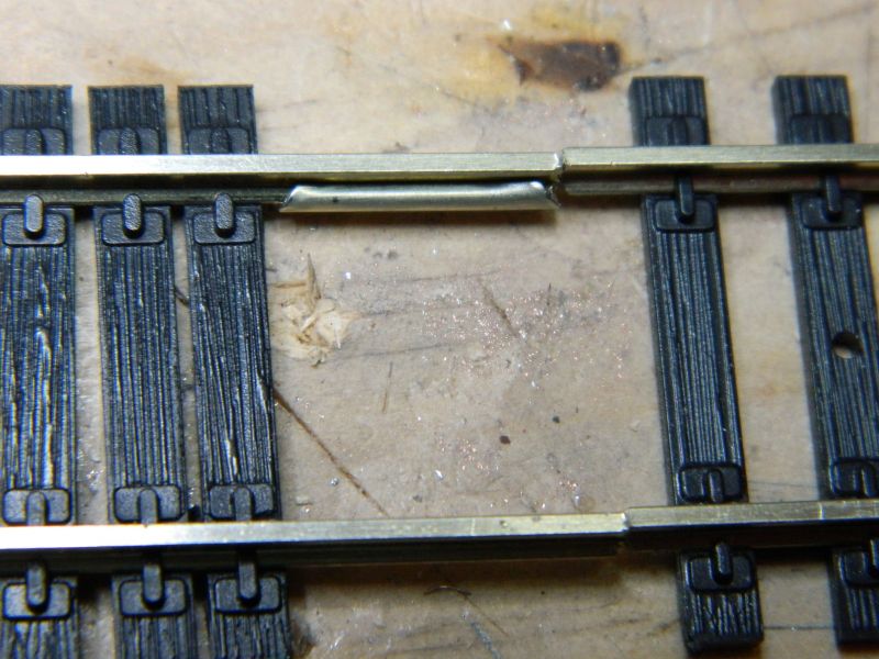
I finally got around to sorting a layout I started ags ago and then left. First thing was to replace an obviously bit of wrong track arrangements which meant inserting a couple of short lengths.I do hate those slide on track joiners, they never seem to slide on. A fair bit of filing of the track end usually helps and life is easier when both bits are clear of the baseboard.
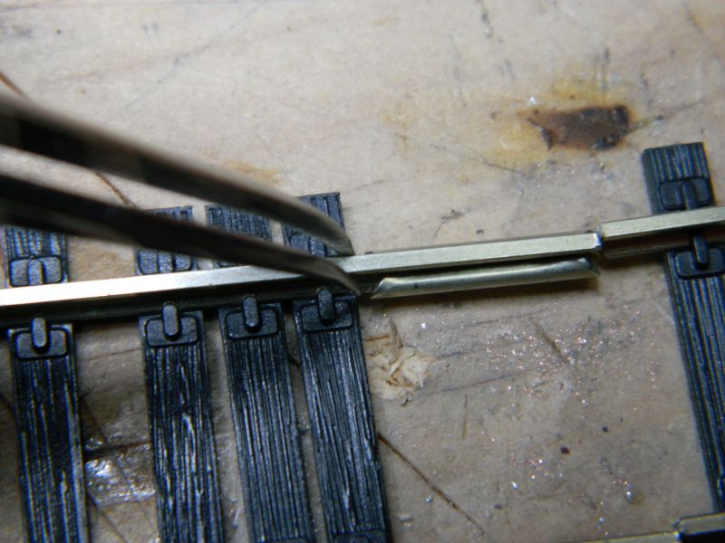
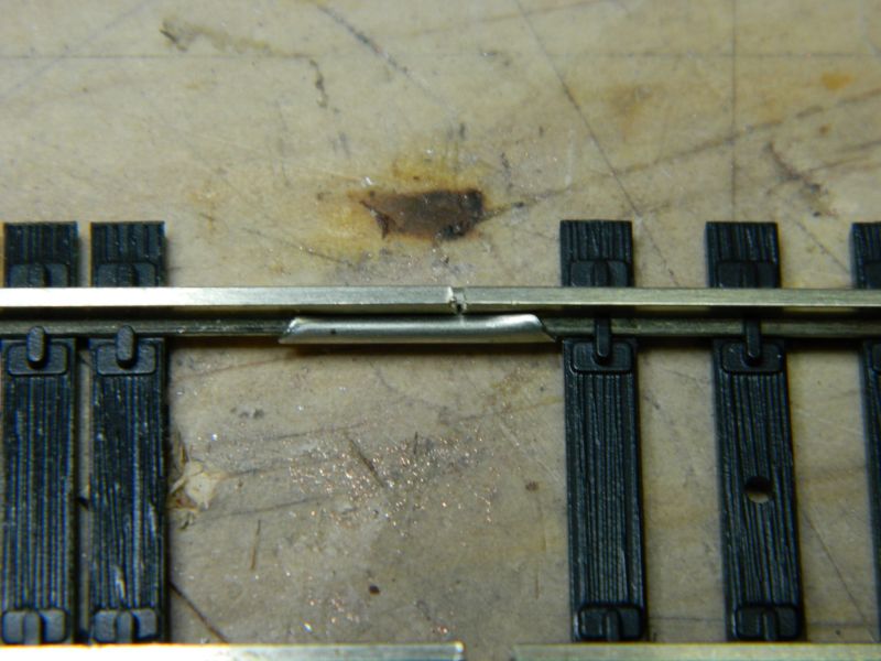
However insering a piece onto track fixed down. On end it was just about possible to slide on, but the other. I opened on end out. Slid the joiners onto the track on the base board then dropped the new track in place and then with pliers gripped the joiner around the new joint. Not the most elegant of methods and not the best looking joint.
It got me wondering as if there is a better way of track joining other than these tight slide on clips. Something where the track is dropped in place and the joiner clammped around both ends. I am thinking of something like a channel and pliers formed to clamp it into the trak section.
Now I have not searched on line so may have missed an obvious solution. If there is one i would appreciating finding out.
Mind you getting the track in place was only the first part of the exercise. Obviously some of the connections and track cleanliness are not what they should be so still more work until it is right.
David
freelance model railways and tramways
index02
index02

Posted

Full Member
Nigel
©Nigel C. Phillips
Posted

Full Member
This might help, though Post #0
'You may share the labours of the great, but you will not share the spoil…' Aesop's Fables
"Beer is proof that God loves us and wants us to be happy" - Benjamin Franklin
In the land of the slap-dash and implausible, mediocrity is king
"Beer is proof that God loves us and wants us to be happy" - Benjamin Franklin
In the land of the slap-dash and implausible, mediocrity is king
Posted
Full Member
It all depends on what the joiners are being used for. Structural integrity, conductuvity, or cosmetic. Once the track is glued and ballasted they are superfluous anyway. Use track pins to position, remove when glue has cured.
Nigel
©Nigel C. Phillips
Posted
Full Member
freelance model railways and tramways
index02
index02
Posted
Full Member
Back home, so some pics of what I do. Hope it is useful.
Nigel
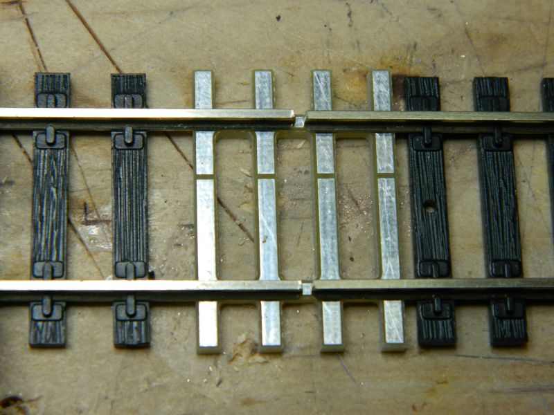
1. When rail is cut with Xurons or similar (especially of well used) knubs are left on the underside of the rail. They need removing with a file. Otherwise the joiners will not slide over.
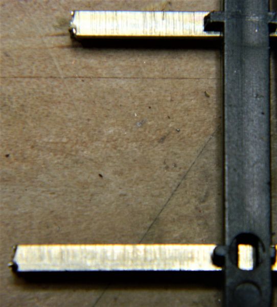

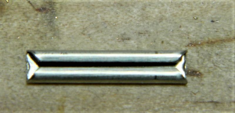
2. Open the joiners up at the ends. I use the head of an old dart. This allows easy fixing. The joiner I used is an Atlas code 83/100, a code 100 is larger.
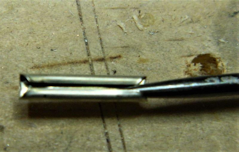
3. Slide the joiner on the ends of the rails of the new section. Cut the webbing underneath to allow the sleepers to be moved along.
4. Slide the rail along with a pair of tweezers. If the rails are aligned the joiner flared end will make sure it goes where it should. Reposition sleepers as required. This technique comes from the Fremo and other modular groups, which use sections of rail 2-6 inches long between the ends of modules. The joiner used is overerly long, adjust length as previously described in the forum, or remove sleepers, cut off spikes, and fix back in place with CA or PVA.
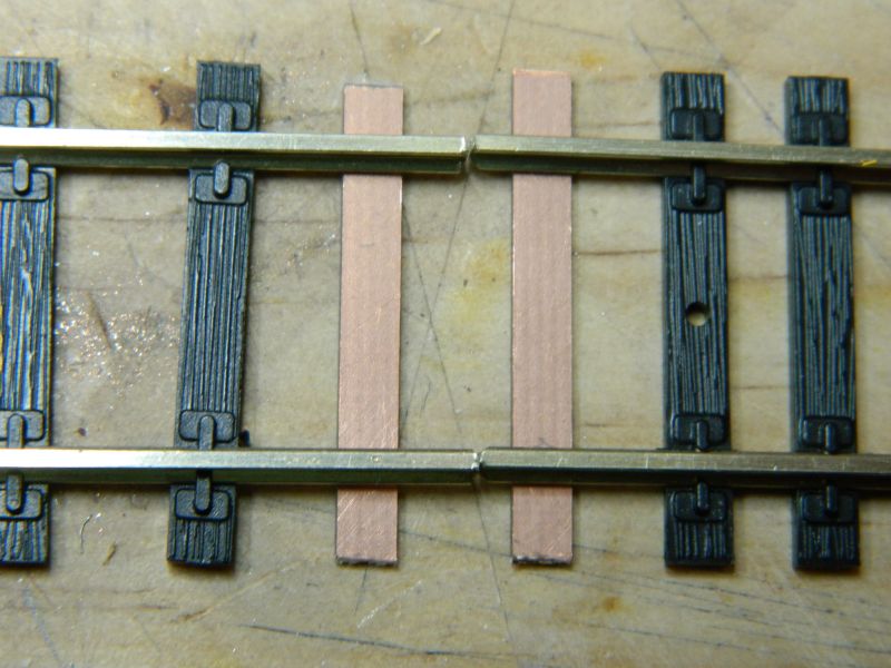
5. These are the pre-tinned sleepers I was talking about.
6. Home made effort using copper clad sleepers, and a bit of brass rectangular rod. Solder the bar to the copper clad ties, turn over, solder the rails to the other side.

©Nigel C. Phillips
Posted
Full Member
In this instance after a few aborted goes the solution is a new bit of track bent between straight connections. Pretty obvious I realise.
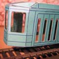
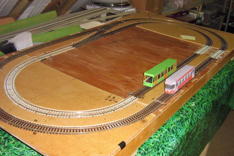
It has however being an interesting learning experience in repairing track already laid and tight bends. Note that the tight bends are due to the layout being for trams. A pair of concentric ovals on a 4 x 2 base is pretty tight and only short wheel bases work over it.
This is the layout when I started it:
YouTube Link: https://www.youtube.com/watch?v=4c_HTFL1HRo&list=PLD9AA9A3100A9BAD3&index=9&t=0s
For various reasons it did not get progressed until I recently decided to sort it out and foumd a few joints needed sorting.
Chassis are all off Underground Ernie, bodies are all card quickies freelance.
David
 Last edit: by wahiba
freelance model railways and tramways
index02
index02
Posted

Site staff
http://yourmodelrailway.net/view_topic.php?id=15402&forum_id=181#p280485
Ed
Posted
Full Member
Flex track on a tight cure, straight rail joiners that do not bend laterally. No wonder you are having problems. What code? How tight? Tramway tight? The only way I know to get rail joiners to curve is by making a series of 3 slits on one side with a Dremel, triangular needle file or fret saw. Do it with the joiner on a bit of scrap rail. Tedious job.
One trick you can do with flex is to give it a light spray with red oxide primer first. That way it will hold the curve a lot better.
If you look at the webbing it is not continuous. That allows it to bend. You can decrease the strain when bending tight curves by removing as much again. Too much curvature and you will pop the rails from the ties. If this is a really tight curve consider moving down to code 75 if you are using code 100. Lot more flexible. If you are already using code 75 then hand laid is the best solution. You can always lock flex to a curve with a few copper clads.
Nigel
©Nigel C. Phillips
Posted
Full Member
Thanks for all suggestions and advice. All duly noted.
David
freelance model railways and tramways
index02
index02
Posted
Full Member
Notice the assortment of track. As i intend filling it in to look tramlike I have used a section of the light concrete sleeper track to the left where it was easier to replace the whole length of track.
Full details under Card Model in the Tram Forum.The Card Tram Posting
Last edit: by wahiba
freelance model railways and tramways
index02
index02
1 guest and 0 members have just viewed this.