Stub points
Posted
#243663
(In Topic #13446)

Full Member
On30 Left hand stub point
Hi All,I decided my On30 plank needed a stub point (or switch or turnout). There is absolutely nothing available RTR, even in narrow gauge, which is surprising as they were fairly common. First time building one of these, so pretty much made-up as I progressed, although there are some helpful reports and how-to's on the web. They were normally operated with a Harp throw lever, although I have seen prototype working examples made from whatever bits of timber and iron rod that were lying around.
This was scratch built using code 83 rail, copper clad EM sleepers (ties) from Markway, with tie spacing to match Micro-Engineering On30 track, and HO scale copper clad seconds for the tie bars from Fly by Night Industries (Clover House). I used a #4 frog and blade jig from Fast Tracks which makes getting the angle and soldering up a really easy job. I downloaded the Fast Tracks #4 On30 template and printed a couple of copies to get the rail positions, and I used 3-arm track spaces and flange way rollers for OO/HO track. The fixed rail sections were attached to the Bass wood using contact adhesive, along with the ties under the moving section. The moving section rails fit into the hinges and are separate from the fixed section.
Nice, easy little project. Now I'm thinking about a catch/trap point. And that On30 3-way turnout I built - stub project? It would make the wiring a lot simpler.
End result of the track laying part shown below with a few notes should anybody want to have a go. Next post will be on the throw lever, as well as the wiring and a bit of detailing..
Nigel
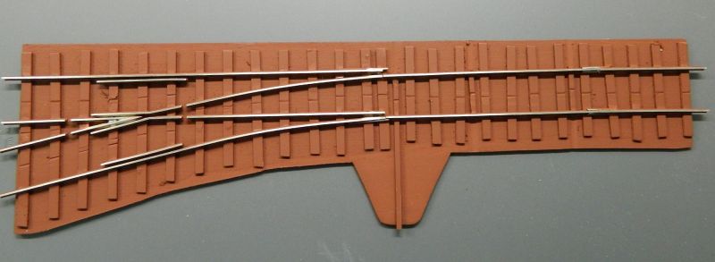
1. Completed turnout glued on a 1/16" thick bass wood board. This cuts easily with a craft knife or similar. The height of the ties and the board matches the tie height on the Micro Engineering On30 flex track. Finished in red oxide primer. I don't bother covering the rails, the primer easily comes off with a scraper blade. My usual frog gaps courtesy of the Dremel and a cutting disk, no need for insulators or in fact to wire the frog. I will however wire the frog (but not connect it) just in case I do model a small wheelbase 0-4-0 or 0-6-0 steam locomotive. It will be a dead/live frog that takes the polarity of the wheels rolling over it. All copper clad ties have an insulating slit, continuity was checked with the meter. Lozenge at the bottom is where the throw lever will go. The moving track is held in place and to gauge with the throw bar and 2 additional bars, seen between the hinges. I will need to wire the rails here at the hinge end to the DCC bus using flexible stranded wire, and to add a removable retaining bar across the throw bar using brass or phosphor bronze wire.
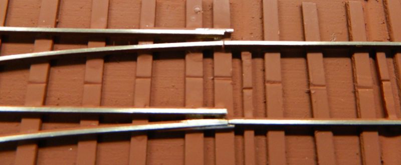
2. Rails thrown for the left hand side exit track.
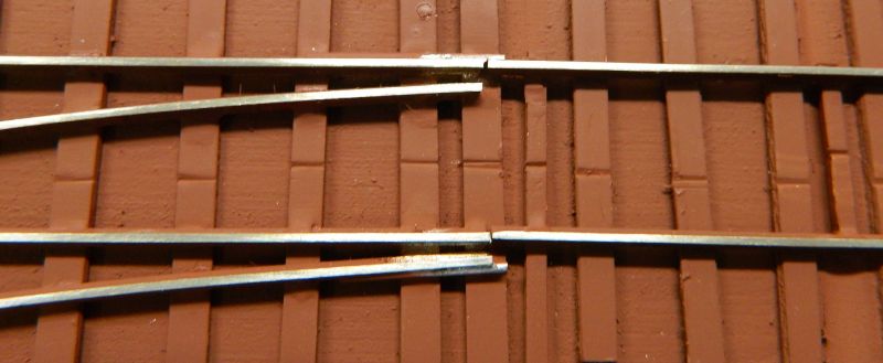
3. Rails thrown for the through track.
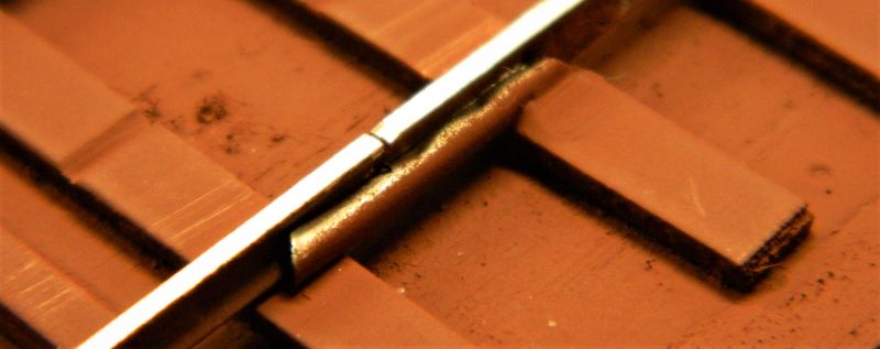
4. Detail of the arresting bars soldered to the web of the fixed rails. These are pieces of 0.04" diameter phosphor bronze rod trimmed to length. No fettling was required as I held the rod in place on both rails using clamps while I soldered.
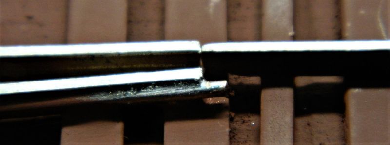
5. The turnout rails are held in place in a fairly loose hinge made from code 83 rail joiners, just enough to allow movement of the rails. The rail joiners are soldered to the rails on the right and to the copper clad ties.
6. Frog details. Bit more solder needed in the frog.

©Nigel C. Phillips

Posted

Site staff
Ron
NCE DCC ; 00 scale UK outline.
NCE DCC ; 00 scale UK outline.
Posted
Full Member
Thanks. About as difficult (or easy) as a regular turnout. The Fast Tracks gadget also puts the correct bevel on the point blades.
Nigel
©Nigel C. Phillips
Posted

Site staff
Ed
Posted
Full Member
I tested the working arrangement with a couple of "module" builds beforehand to iron out any issues. I was a bit concerned with the #4frog and exit radius, an 0-8-0 may have difficulties. The 0-6-0 should be OK.
Nigel
©Nigel C. Phillips
Posted
Full Member
Forgot to take these photos yesterday. May make the method used clearer.
Nigel
1. Point "blades" removed from the stub turnout. The slight opening of the rail joiners can be seen. Simple operation to remove the rails - elevate slightly then pull out of the joiners. The eagle eyed will note that the joiners are not the same length, not an error, that is to facilitate putting the removable section back in. Easier at a slight angle than straight in.
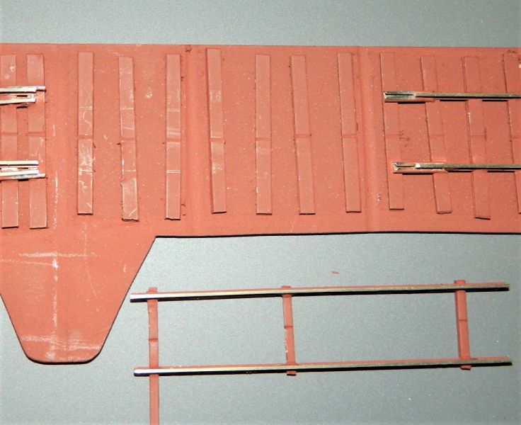
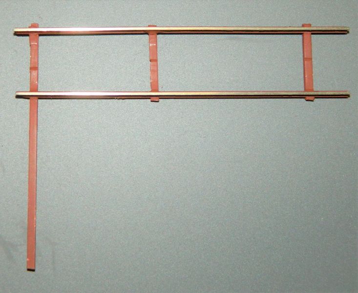
2. Close up of the removable section.The rails are held in gauge by the throw bar and two additional tie bars that sit between the regular ties.There is a slight depression in the bass wood as the bars are double sided copper-clad and slightly thicker than the regular ties which are single sided copper-clad. The ends of the bars will be filed down a bit more so they are almost flush with the rails. Difficult to see, but I solder both sides of the rail. Detailing to come.
©Nigel C. Phillips
1 guest and 0 members have just viewed this.