Manual Point Control
Posted
#152989
(In Topic #8534)

Inactive Member
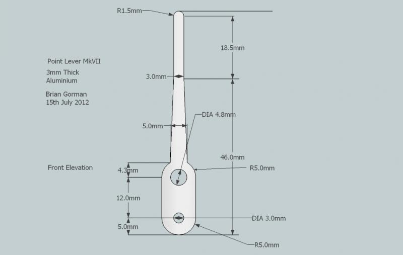
Stage 1 The Lever
G`day Folks,The system I will employ for point control on my railway , Great Chesterford Junction, will be mostly manual control. It would be far simpler to just use solenoid point motors, however I have found I love the feel and operation of a manual system. It`s like you are there in the signal box being alert and responsible for that section of railway and it adds considerably to the experience.Originally , the levers were hand cut from 3mm x 10mm Aluminium Flat Bar and there is no reason why that should not still be the case, however, because of the shape I had chosen, I found it difficult to achieve consistency whilst cutting and shaping them. In the end , I bit the bullet and had them Laser Cut. I smooth down the edges and countersink one of the holes but that is all that is required.The next step is to add hardware for linkages. I have found terminal block inners ( Choc Blocks for English readers) to be quite effective and simple. They are cheap and allow for adjustment as well. The photographs below show a completed lever ready for the next stage.


I will post a drawing with measurements in Stage 2 Cheers for now Gormo
"Anyone who claims to have never made a mistake, never made anything!!"
https://sites.google.com/site/greatchesterfordmodelrailway/home
https://sites.google.com/site/greatchesterfordmodelrailway/home

Posted

Full Member
Welcome to the club,
Being from the other end of the spectrum with computer control I find this manual approach fascinating stuff - I will watch with close attention as it evolves
:cheers
Posted
Inactive Member
I`m glad you`re interested………it will get better…….I promise
 Last edit: by gormo
"Anyone who claims to have never made a mistake, never made anything!!"
https://sites.google.com/site/greatchesterfordmodelrailway/home
https://sites.google.com/site/greatchesterfordmodelrailway/home
Posted

Full Member
Looking forward to this as I intend to use manual point control on my layout
Regards
Stephen
Acording to a recent visit to a supermarket at check out time, I an not loosing my memory it has been downgraded which means i am not stupid afterall - Sorted! - What a relief
Posted

Full Member
Marty
Posted
Inactive Member
G`day Folks,This system of manual control consists of a lever, as shown above, which pivots on a suitable length of 3/16" threaded rod. The rod is suspended by a small right angled bracket at each end. The position of the lever ,relative to the rod within the lever frame , is maintained by using flat washers and Nyloc nuts.The lever frame can be as many as 15 levers ( have not tried that many but am sure it would work !)…….it just depends on what you want to do. The frame can be mounted on top or on the side or below the baseboard. On my layout the lever frames will be mounted below baseboard and this will necessitate fitting rocker arms to the back of the frame. This will transfer the movement of the lever to the rocker to the underside of the baseboard. The pictures will show this more effectively.Rod or cable can be connected to the lever / rocker. On a straight run , the cable or rod would travel to below the point location where it will be connected to a sliding rod within a modified half hinge of suitable size. The other end of the sliding rod will have a small rivet attached via a terminal block inner. The rivet passes up through the baseboard and through the tie bar of the point.On a run of cable or rod that requires a change of direction , I employ bellcranks made from plastic quad / moulding…..more about this later.
The first frame I have built, apart from the test dummy, is a 10 lever frame as documented below.
First of all, parts had to be altered and some manufactured………so we start with the Rocker Arms…..made from 10mm x 3mm Aluminium Flat Bar…which will go on the back of the frame

They are then fitted with terminal block inners and washers


Next the levers are finished off and given their appropriate fittings


Now we can start to put a frame together. A calculation for the length of Rod required is done and the Rod cut to length. Start from one end ,locking down the bracket and hold the lot in the vice. The levers are added one by one and tension on them adjusted as they are fitted. The observant amongst you would have noticed a bottle of Loctite in a pic above. I am using it as a bit of insurance. I don`t want anything moving or slipping and I don`t want to have to take the frame apart on a regular basis……..Therefore " Loctite "
 A
AA completed frame

Then onto the Rocker Arm frame which is the same process as the Lever Frame…….same washers, brackets , rod etc……


The whole lot is then housed in a timber box. I have chosen 90mm x 20mm Radiata Pine….it`s the cheapest in Oz. The box will have a removable front to allow access to the Levers from above. The removable front will also have the combing attached to it.The next pic shows parts laid out ready for positioning of the frame

Screw holes pre-drilled and countersunk where necessary

The next shows the lot coming together

I still have to fit some Aluminium angle to the back board. This acts as a stopper for the Levers going forward and also as a rest for the combing. Further Aluminium angle will be sat on top of the removable timber at the front of the box. The combing will be attached to this part. Obviously the box needs some dressing up and finishing …….but I`m getting there.More to follow…….hopefully tomorrow…………Cheers Gormo
"Anyone who claims to have never made a mistake, never made anything!!"
https://sites.google.com/site/greatchesterfordmodelrailway/home
https://sites.google.com/site/greatchesterfordmodelrailway/home
Posted
Inactive Member
I forgot about the drawing…….here it is…..Cheers Gormo
"Anyone who claims to have never made a mistake, never made anything!!"
https://sites.google.com/site/greatchesterfordmodelrailway/home
https://sites.google.com/site/greatchesterfordmodelrailway/home
Posted

Full Member
Beyond my capabilities though - I'm gonna have to stick with wire-in-tube…
Great stuff, Gormo!
Shaun.
Posted
Inactive Member
It`s not as hard as it looks……it`s just a build up of simple processes that makes it look complex.
Cheers Gormo
"Anyone who claims to have never made a mistake, never made anything!!"
https://sites.google.com/site/greatchesterfordmodelrailway/home
https://sites.google.com/site/greatchesterfordmodelrailway/home
Posted

Legacy Member
Posted
Inactive Member
G`day Folks,I have moved on a bit from yesterdays update.But first a couple of pics ……..they give some better views of this thingamajig, in particular the short connecting rods between the levers and rocker arms.


We now move on…Today, the first thing to tackle is the Aluminium angle support for the combing…….and this is to be placed on the back board above the lever bracket. A section had to be taken out of each side of the angle for it to clear the brackets and fit properly.


I also needed to create a spacer for the support so that the levers would be vertical at their end stop in the forward position. The spacer fits behind the angle. Note the matching screw holes.

The next piece of the jigsaw was the Aluminium angle for the front piece of timber. The combing will be glued to this.


Cutting the combing pieces came next and some trial fitting. The combing is cut from 25mm wide Aluminium Arched bar which is readily available from the hardware store.


Note the temporary spacers at the back to give me something to line up the combing. Next the combing was Super glued in place but only on the front piece. This allows the combing to be removed easily because it is all attached to the front timber.Finally it`s finished……….there is still sanding and finishing and detailing to be done……but in essence this is it. I should point out too that this frame is intended to be mounted below the baseboard……..hence the Rocker Arms as mentioned earlier in this article.


The next stage will deal with detailing the box and levers…………Cheers Gormo
"Anyone who claims to have never made a mistake, never made anything!!"
https://sites.google.com/site/greatchesterfordmodelrailway/home
https://sites.google.com/site/greatchesterfordmodelrailway/home
Posted
Legacy Member
Posted

Full Member
I note you had the levers made - presumably in bulk and by stamping out of a sheet. To reduce the individual costs, do you have any plans to market this frame ? If so, I think you might get a few takers ………………….:roll::roll:
'Petermac
Posted

Full Member
More…Encore…Author….
Doug
'You may share the labours of the great, but you will not share the spoil…' Aesop's Fables
"Beer is proof that God loves us and wants us to be happy" - Benjamin Franklin
In the land of the slap-dash and implausible, mediocrity is king
"Beer is proof that God loves us and wants us to be happy" - Benjamin Franklin
In the land of the slap-dash and implausible, mediocrity is king
Posted

Full Member
Always try to look on the bright side of life!
Barney
Barney
Posted
Inactive Member
The Levers are the only part that was manufactured for me. They were Laser cut. It seems to be the simplest and cheapest way I know of to have something like the the lever made. I had to supply the company with a drawing. They, in turn copied my drawing into a format that the Laser`s computer could read. The drawing is then archived in case I need more made in the future. The Laser`s computer then works out the most efficient way to "Cut" the levers from a sheet of 3mm Aluminium.
Obviously, the more you have made, the cheaper it becomes. I had a hundred cut and I thought I would sell on anything that was excess to my needs. I tried to sell 10 levers and fittings on Ebay but to no avail……so I have temporarily given up on that idea.
The original thinking behind this system was that you could go out to your hardware store and buy most of the bits required. That is perfectly true, and when I draw myself back to the original concept, I designed it for the hands on home builder.
So …..at the moment…….I am putting the information out there for fellow railway modellers to use and adapt because ultimately it works out a lot cheaper than the very elegant commercial systems currently available and I look on it as my contribution to the hobby.
The following shows the levers and rocker arms working http://www.youtube.com/watch?v=blxs8geaxQs
Cheers Gormo
Last edit: by gormo
"Anyone who claims to have never made a mistake, never made anything!!"
https://sites.google.com/site/greatchesterfordmodelrailway/home
https://sites.google.com/site/greatchesterfordmodelrailway/home
Posted
Full Member
How much were you trying to sell the levers for on ebay?
Regards
Stephen
Acording to a recent visit to a supermarket at check out time, I an not loosing my memory it has been downgraded which means i am not stupid afterall - Sorted! - What a relief
Posted
Inactive Member
It is not really a bother…….I will try again at some later date……I have not lost any sleep over the matter.
Cheers Gormo
"Anyone who claims to have never made a mistake, never made anything!!"
https://sites.google.com/site/greatchesterfordmodelrailway/home
https://sites.google.com/site/greatchesterfordmodelrailway/home
Posted
Inactive Member
G`day Folks,
Well now we get to the painting and varnishing stage. So everything is taken apart.
The combing is fragile and has to be handled carefully.

The combing and brackets are laid out and sprayed matt black.

The timber is varnished. The first coat will be rubbed backed with fine steel wool and re-coated. A third coat will follow if necessary.

The levers are painted with artists acrylic paint by hand. I wanted the hand painted look.


After the painting and varnishing process we move on to labelling and assembly.
The labels are created with one of the new generation Dymo labellers using a metallic tape.


I have gone for the old but cared for look with the varnish. It`s something I learnt at a french polishing course a few years ago. You apply your finish ( varnish or shelac ) let it dry thoroughly, rub it back with fine steel wool to a dull finish. Then you apply beeswax and rub it in well and buff it off. You finish up with a satin finish instead of gloss. I prefer it……but that`s me?????
Anyway….more to follow……..Cheers Gormo
"Anyone who claims to have never made a mistake, never made anything!!"
https://sites.google.com/site/greatchesterfordmodelrailway/home
https://sites.google.com/site/greatchesterfordmodelrailway/home
Posted
Full Member
 thumbsthumbs
'Petermac
1 guest and 0 members have just viewed this.