Dentith Bridges Underlying Technology
Posted
#256117
(In Topic #14044)

Site staff
The development Dentith Bridges Digital Control and Accessory Control
Hi All,
This thread will be developed in parallel to my Dentith Bridges thread and will be dedicated to the more technical aspects of the layout development.
More to come
Cheers, Andrew :cheers
Wasnie me, a big boy did it and ran away
"Why did you volunteer ? I didn't Sir, the other three stepped backwards"
"Why did you volunteer ? I didn't Sir, the other three stepped backwards"

Posted

Full Member
Hi AndrewDCC - NCE and DCC Concepts booster - this may turn out to be a limiting choice
Will use a Mimic panel to control routing but hope to introduce automated control at some point. To this end block detection will be a feature
Layout will be three levels - lowest level Fiddle yard and storage. Middle level perimeter incline/decline from the fiddle yard to the upper level. Upper level main station, multi platform, goods facility, engine shed, turntable and industrial setting.
Andrew
Sorry for the delay in responding to this post. I have been controlling my layout automatically for over 10 years. I am addicted to it although its not to every ones taste. I am delighted to find a potential fellow enthusiast
 and more than happy to share my experiences.
 Here are a few initial questions/comments
this may turn out to be a limiting choice…….. could you expand a little on that?
Will use a Mimic panel to control routing….. if you eventually opt for automatic control, routes will be set by the software and all turnout will be wired to a DCC accessory decoders. It would be prudent to take this into account when wiring your panel.
Granby is quite a large layout but when I started I built just a small section with six turnouts. I wired them to both a mimic panel and a DCC decoder. I then pottered about on this while I determined whether I was going to invest in computor control. After I crossed that Rubicon I continued to create duplicate set ups switchable between a manual panel and a DCC decoder. After a while I realised the mimic panels were redundant and I now use either the computor screen or the DCC throttle.
Note: If I did not have RR&Co I would not want to rely solely on DCC decoders to throw turnouts…..too cumbersome
To this end block detection will be a feature Have you decided what system you will use? Most people use some form of current detection. If you opt for this, it is a good idea now to feed +ve track droppers (clearly identified) to an accessible intermediate connection before connecting them to the +ve DCC bus. This actually makes sense for fault finding but will make the later creation of detected blocks relatively simple.
I can see that you have already done a great deal of research so I apologise if this is already covered.
You may not want to clutter your layout thread with the technical stuff in which case I suggest starting a separate thread and we can get a mod to move this reply there.
Best wishes
Posted

Full Member
Posted
Full Member
[user=2199]Andrewdonald[/user] wrote:Hi AndrewDCC - NCE and DCC Concepts booster - this may turn out to be a limiting choice
Will use a Mimic panel to control routing but hope to introduce automated control at some point. To this end block detection will be a feature
Layout will be three levels - lowest level Fiddle yard and storage. Middle level perimeter incline/decline from the fiddle yard to the upper level. Upper level main station, multi platform, goods facility, engine shed, turntable and industrial setting.
Andrew
Sorry for the delay in responding to this post. I have been controlling my layout automatically for over 10 years. I am addicted to it although its not to every ones taste. I am delighted to find a potential fellow enthusiast
Here are a few initial questions/comments
this may turn out to be a limiting choice…….. could you expand a little on that?
Will use a Mimic panel to control routing….. if you eventually opt for automatic control, routes will be set by the software and all turnout will be wired to a DCC accessory decoders. It would be prudent to take this into account when wiring your panel.
Granby is quite a large layout but when I started I built just a small section with six turnouts. I wired them to both a mimic panel and a DCC decoder. I then pottered about on this while I determined whether I was going to invest in computor control. After I crossed that Rubicon I continued to create duplicate set ups switchable between a manual panel and a DCC decoder. After a while I realised the mimic panels were redundant and I now use either the computor screen or the DCC throttle.
Note: If I did not have RR&Co I would not want to rely solely on DCC decoders to throw turnouts…..too cumbersome
To this end block detection will be a feature Have you decided what system you will use? Most people use some form of current detection. If you opt for this, it is a good idea now to feed +ve track droppers (clearly identified) to an accessible intermediate connection before connecting them to the +ve DCC bus. This actually makes sense for fault finding but will make the later creation of detected blocks relatively simple.
I can see that you have already done a great deal of research so I apologise if this is already covered.
You may not want to clutter your layout thread with the technical stuff in which case I suggest starting a separate thread and we can get a mod to move this reply there.
Best wishes
Hi John,
I am pretty much lined up with your "thought processes and approach", but in the very early stages of development. My broad intentions are as follows (sorry if this is a bit long to read, perhaps you or a moderator could suggest a place to establish at Dentith Bridges Technical Details thread)
- The multiple level approach lends its self quite nicely to a learn as you go approach - as you did, I will start with the fiddle yard on the lower level, slowly building up the complexity of the points network as I gain confidence, just a few points will do to start with
- With regard to my comment re a limiting choice, I am/was concerned that the lack of a USB/Serial connection for the PowerCab would be an issue. I have since obtained the NCE USB interface and have tested it with JMRI, using both a Windows platform and a my preferred Mac platform and it works just fine. I do note however that the RR&Co website specifically mentions NCE Power Pro and not the PowerCab.
- I intend to run a dedicated DCC power bus for the track, employing a number of power districts protected via circuit breakers, a dedicated DCC accessory power bus and a dedicated low power DC bus for none DCC stuff (lighting and such) and to provide a power supply for the Megapoints Controller network that will manage remote control of points, point status feed back and occupancy feed back.
- The Megapoints Controller network will, eventually, also have a DCC interface that will enable DCC control and Megapoints control. The Mimic panel will be "driven" by a Megapoints Multi panel processor that will enable direct push button control of points, but will also respond to remote switching of points (via DCC) and will indicate the state of the points and will also provide occupancy feed back.
- Occupancy will be detected using Megapoints occupancy detectors which a current sense detectors that sample current on the appropriate track feeder wire.
- I intend to employ a modular wiring layout design and I am looking forward to the wiring aspect of the build.
- For the fiddle yard I will be using Cobalt IP digital point motors, so DCC control will be available straight out of the box. I will also have Megapoints point motor drivers, thereby enabling the dual control capability.
- For the middle and upper levels I will use MTB1 point motors, again driven by Megapoints point motor drivers. I chose the MTB1 motors primarily for their very low profile so as not to overly impact on the track layout design due to headroom constraints.
- At this point I have not decided which control software I will use (I won't need it for some time yet and I need to do some more research in this area), but I am keen to here about any advice you and the rest of the forum group might have to share - one decision I have already made in this regard is that I will not be using JMRI.
Cheers, Andrew :cheers
Posted
Full Member
I can only echo what John has said really. It's important to decide what aspects of a layout are your key areas. Like John (and with advice from him along the way) I went down the Railroad & Co software route with full block detection and automated points. I enjoy the electrical side, automating operation and the basic build less so the scenics but I think getting it stright in your head what the eventual aim is with your layout can save so much time (and money) along the way.
Thanks Dave,
Please see my response to John. I think the scenery production is going to be a challenge for me - low on skill set and patience think……… :roll:
Cheers, Andrew :cheers
Posted
Full Member
As I suspected you have done a lot of research. That is a very comprehensive spec.
At this point I have not decided which control software I will use (I won't need it for some time yet and I need to do some more research in this area), but I am keen to here about any advice you and the rest of the forum group might have to share - one decision I have already made in this regard is that I will not be using JMRI.
If you are going to buy a software package the choice is probably going to be between RR&Co and Itrain. Both systems allow you to download the software (and manuals) and operate the system live and in demo mode…….there are time limitations in live mode.
I would encourage you to download both systems or at least the manuals. Once you are certain that computor control is a must, there are a number of strong arguments for purchasing the chosen system immediately and developing it in parallel with the track installation rather than waiting until the last spike.
I purchased mine while working on the branch…….18 month embargo on loco purchases :shock:
…….I now regret not spending more time working with it on the trial layout before pressing on with the main layout. Its a steep learning curve and the lessons learned can influence block structure and the number of occupancy detectors requiredBest Wishes
Posted
Full Member
I will down load the demo software and manuals in the next few days.
Cheers, Andrew :cheers
Posted
Full Member
ExcellentThanks for the excellent advice John. As you say, now is an opportune time to "experiment" as it is very early days.
I will down load the demo software and manuals in the next few days.
Cheers, Andrew :cheers
RR&Co Train Controller comes in three flavours Bronze Silver and Gold. You will find Bronze lacks too many features. I suggest you download Gold TC and the Gold/Silver manual which has the differences between gold and silver highligted. Other than those two you dont need any of the other software for your evaluation
I think Itrain has a a similar structure so download the premium set
A guy called Rudy has done about 50 excellent TC tutorials on Youtube. There are itrain videos on Youtube also.
Have fun
Posted
Full Member
The block diagram of the Megapoints Controllers network is shown in the enclosed PDF file. As it turns out I did not realise that the DCC interface is only one way. In other words I cannot get feed back from the network to the NCE USB interface and then to the controlling software.
Dave Fenton of Megapoints tells me that they are working on a JMRI interface but he does not know when that will be ready for production. (I am not keen on JMRI anyway).
One option I am investigating is the possibility of interfacing the Digikeijs 4088 with my NCE/DCC concepts booster. But I don't hold out too much hope.
Posted
Full Member
I guess it will not affect your turnouts because most people dont think turnout position reporting is essential but it does limit your options in regard to occupancy detection. Will the Megapoint Controller accept feed back from another occupancy detection system?The block diagram of the Megapoints Controllers network is shown in the enclosed PDF file. As it turns out I did not realise that the DCC interface is only one way. In other words I cannot get feed back from the network to the NCE USB interface and then to the controlling software.
Posted
Full Member
Yes, I am pretty sure it will as long as the out put from the detector is basically a 5volt DC short to ground.
There are diagrams at the end of this document that show how the sensors are linked to the feedback board. FeedbackModule-user-guide.pdf
Cheers, Andrew :cheers
Posted
Full Member
A quick update on the Megapoints Controls implementation - in particular displaying turnout/points position feedback to a mimic panel by way of a pair of bi colour leds. i.e. both leds always on, one green, one red. As the turnout/point is thrown, the leds "change colour" indicating the route available.
Underlying tech is MP's multi panel processor (mpp), feed back module, voltage sense board and a led expansion board, together with an Arduino microprocessor. The Arduino is used to detect the signal hi and low sent to the led expansion board via the feedback board and the mpp. As the Arduino "senses" the change in signal, it activates the red/green or the green/red combination as required. - The MP set up is not able to do this for "real time feedback", it is only able to do it for sent switch commands.
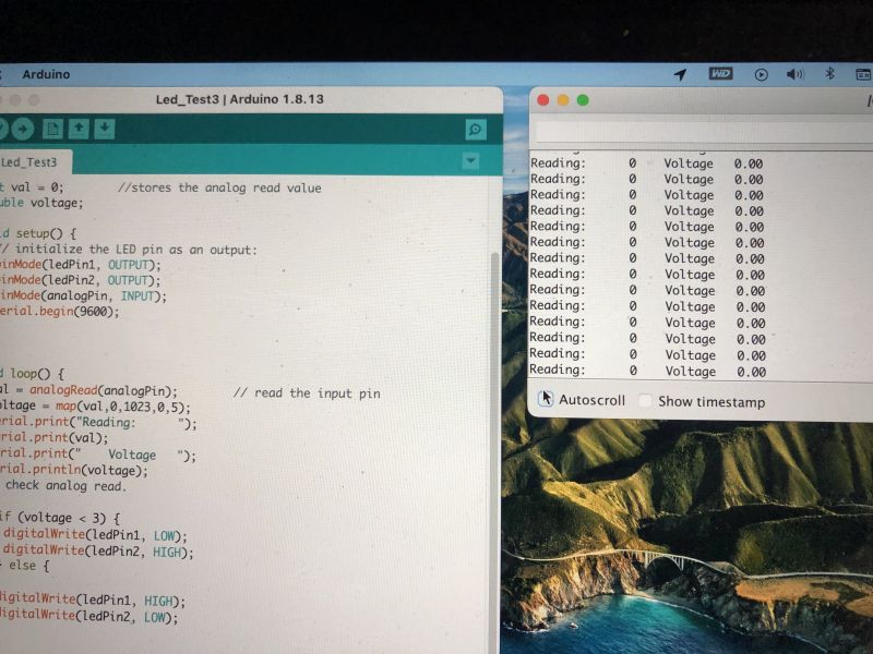
These next two pictures show the system sensing track power across the point/turnout (see MP web site for wiring details) #1 shows the leds lit, (upper right side of the picture) #2 shows what the Arduino "sees".

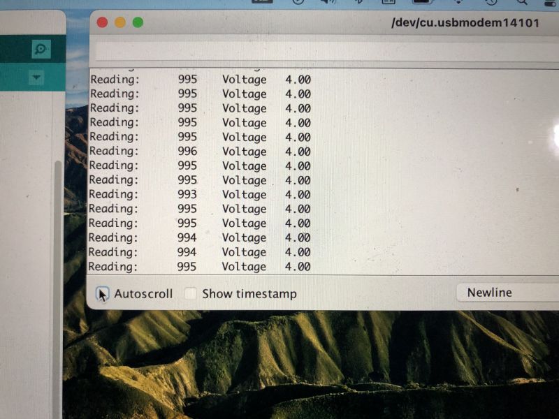
These next two pictures show the system sensing no track power across the point/turnout (see MP web site for wiring details) #1 shows the leds lit in reverse, (upper right side of the picture) #2 shows what the Arduino "sees".
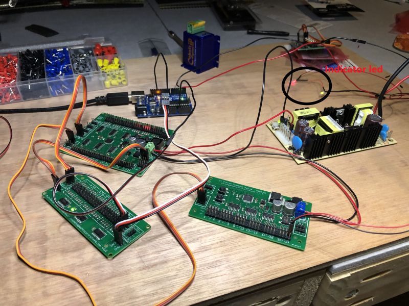
Apologies for the poor state of the wiring, no breadboard to hand, but was itching to get the scheme working :thumbs
Tomorrow, I will clear off the "rat's nest", put the board on its side and get the wiring phase started. The plan is to get one point motor installed and wired up and tested, end to end, with the above scheme, the beginning of the accessory bus, the track bus and the low power DC bus (driven by a robust 24 volt 10 amp supply with appropriate DC-DC step down converters as required.)
Hopefully I can make another report after Anzac Day - big weekend coming up for me.
Cheers :cheers
Posted

Full Member
Does the below mean that the system won’t be able to confirm that the blades of the turnout have thrown correctly?
The MP set up is not able to do this for "real time feedback", it is only able to do it for sent switch commands.
 Last edit: by Marty
Posted
Full Member
No, it does confirm the position of the blades. I probably did not explain myself properly. The detector, if hooked to the point correctly, will detect the actual position of the blades, straight through or thrown. The issue is with the indication. Using the feedback module, connected to the mpp network, point detector (voltage sense across a stock rail and a switch rail) and the led expansion board, the system can then toggle a pair of leds on/off, indicating the actual route set on the points.[user=2199]Andrewdonald[/user] wrote:
Does the below mean that the system won’t be able to confirm that the blades of the turnout have thrown correctly?
Feedback indication
However, I wanted to use a pair of "bi colour" (red/green) leds, so green shows selected route, red shows blocked route. To use the bi colour leds requires the led expansion board to be connected to the "led compliment " (reverse voltage) connector on the mpp board and not the feedback connector. There is no compliment capability on the feedback connector. Using Bi Colour Leds From the video you will see you get an indication when you remotely switch the points, but this is reporting what your requested, not what the point actually did. In the video you will notice that there are no points connected to the demo system.
I really like the multi colour indication for the real state of the points, not just what was requested - Grand kids fingers moving points………. :It's a no no I like to see a positive yes (green) and a positive no (red). Anyway, I went ahead and purchased the system and figured out a work around. Let the Arduino receive the indication via the network and have it toggle the leds as required. The Arduino can handle six pairs of leds, so I will have two for the lower level and probably two for the upper level. The other good thing is that the Arduinos will sit inside each of the mimic panels along side the panel processor and led expansion board which will be used for indicating block occupancy as well as proving point data to the Arduinos. I might also be able to find additional uses for the Arduinos:hmm (An Arduino will certainly control my turntable, when I get to that point in the build.)
So short answer, sorry, the system does detect the position of the blades, but I wanted a different status indication using the bi colour leds. Clear as mud I guess
Cheers :cheers
Posted
Full Member
My layout is DC and my point control system is totally analogue using a single large relay with 3 output circuits for each set of turnouts. The SEEP solenoid point motors have an auxiliary switch circuit that is driven by the point actuating rod being thrown, that feeds my relay which then changes the point frog polarity (1) and changes the voltage/current direction via resistors of the bi-colour LEDS, Straight (2) or diverge (3). (at least, it's been a while since I wired them up and I think that is how it works, there is a description in my layout thread somewhere).
I mostly follow how your arrangement works. I think that your tortoise motors have the same auxiliary output. Programming with the Andruino looks fun… something I'm hoping to play with later on.
My Llandyfriog junction has six points controlled from this panel. You can see one of the relays (circled in red) sitting on the L-girder.

Keep it coming, really enjoying your comments regarding the MP set up.
Last edit: by Marty
Posted
Full Member
Well as I said over on Dave C's blog, his turntable discussion has really got me motivated… I have always intended to have a turntable on my layout and it is part of the layout plan. I also wanted to make the TT a DIY project. So, I drew the prototype design up in Fusion 360 ( a very nice cad/cam tool)

The full table.
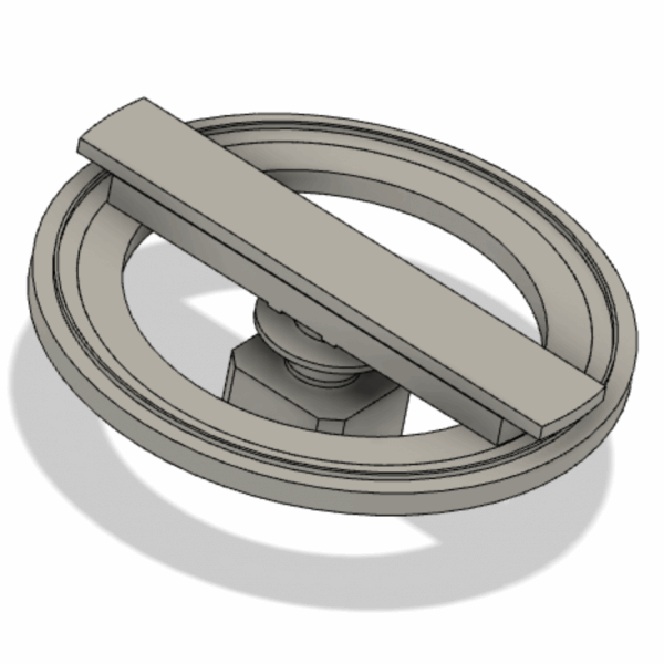
Without the pit floor and wall, showing the overall concept.
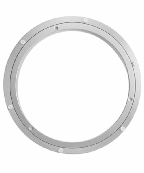
An aluminum Lazy Susan base will form the chassis for the turntable. The outside ring will be fixed, the inside ring will rotate
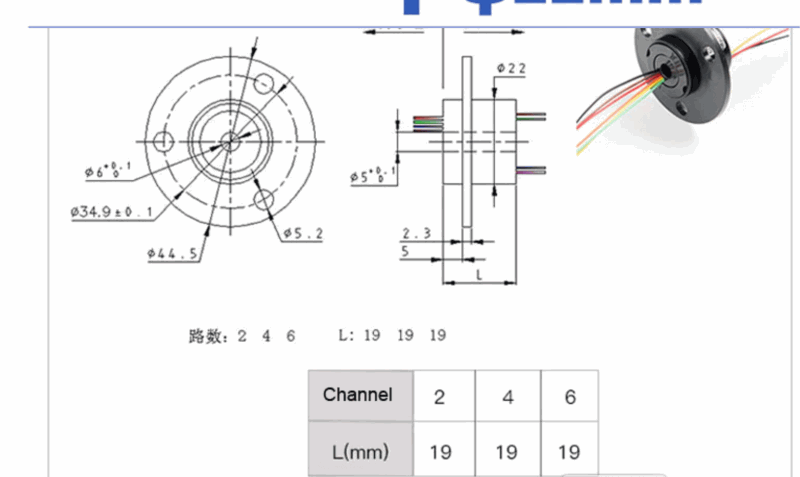
Power will be fed to the bridge track via one of these neat slip rings. I will use the 6 channel. I only need two for the track, but the other four wires might come in useful for something else, lighting perhaps? The design calls for two sensors to 1) enable the zero position for the bridge (stepper motor) to be able to be found and 2) to switch the polarity of the bridge track as required. Switching to be achieved via two solid state relays. I am not sure yet what type of sensors I will use. Any suggestions?
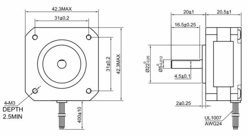
Currently I am thinking of using this "pancake" Nema 17 stepper. Plenty powerful, but has the added advantage of not requiring as much space below the track. I will also research the smaller steppers as well. At this point I will use the easy driver board.
The entire turntable will be controlled via software running on an Arduino Pro Mini micro controller. Overall command will be exercised via a turntable control/mimic panel, the design of which is yet to be finalised. My initial thoughts are tending towards a rotary switch in the centre of an etched plate with red and green led at each position of the switch to indicate bay availability, green available, red occupied. (not really needed as the operator will be able to see the turntable - but it will look cool for the grand kids!) The Arduino will provide expansion capability for things like round house lighting and so on.
Now all of this is quite some time off yet for realisation, but I hope to do some prototyping,in the near future with some bits and bobs I have to hand. I am keen to begin developing the code and incorporating the sensors, at this early stage I will use limit switches to simulate/emulate the sensors. (Or I could simply use push buttons).
Anyway, all good thoughts. In the meantime I have recommenced work on the underside of the boards, so more to come in that area after the weekend.
Cheers
Andrew :cheers
Posted
Full Member
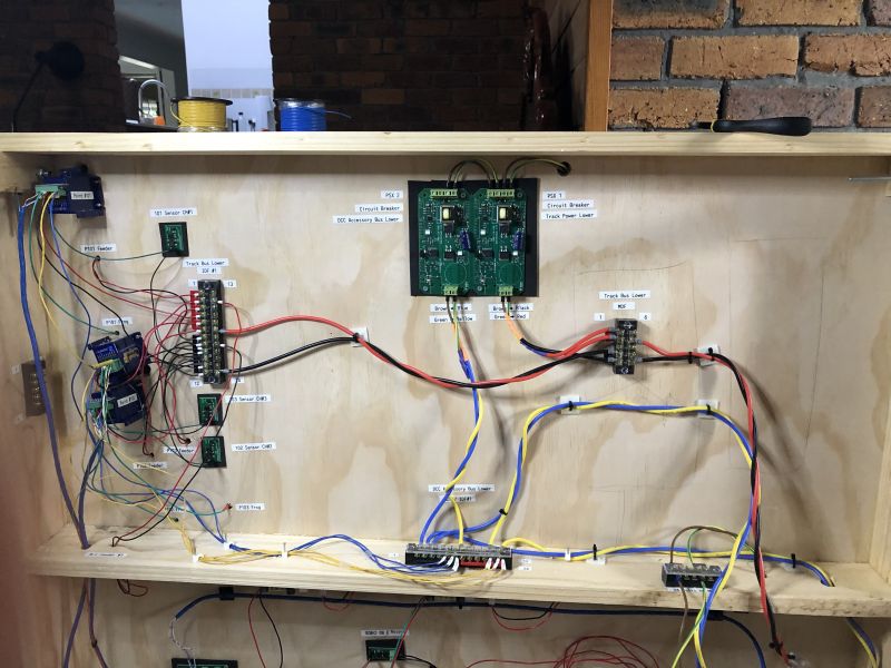
Here we see one half of the board. The two large green board at the top of the picture are PSX circuit breakers (fast acting digital breaker) One is currently protecting the DCC Accessory Bus (blue and yellow) and the other is protecting theTrack Power Bus (Red and Black) - Apologies for the harlequin colours on the pigtails into the breakers, I do not have the appropriate coloured heat shrink - this will be attended to in due course. Lower right you can see the extension of the buses that are terminated in a "chocolate block" for connection to the neighbouring board. (sorry I cut the connector out of the shot) The smaller green boards are the Mega Points Controllers (MP) sensors for block occupancy and turn out status. As the next board progresses topside next week, I will add in a dedicated feed back bus to bring track droppers back to the appropriate sensors as required. (right now there is only one dropper per block detector, as the blocks increase in size, more droppers will have to come back to the sensors)
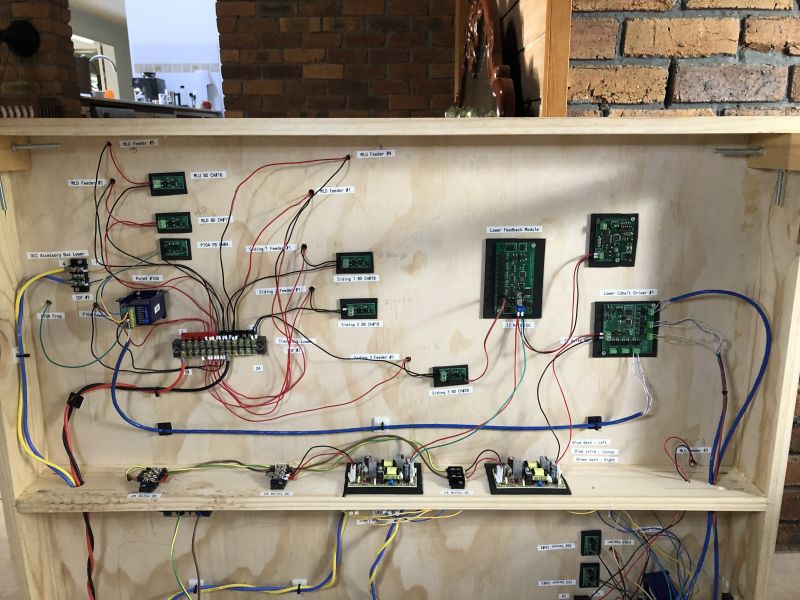
Here we can see more of the MP network. Centre and left we have more sensors. To the right we have the Feedback board, the Cobalt driver board and above it the first CAN bus node. The feedback and driver boards are linked over a simple local I2C network. (connecting cables not in place yet, I have to manufacture them). As the layout grows there will be other local networks around the layout. These local networks will all be connected via a CAN bus. At this stage, the CAN bus will extend from this board to a temporary "mimic panel". (All of this "black magic" is well explained on Dave's MP site.)
On the "shelf" you can see the beginning of the 24/12 Volt DC distribution bus. 24 Volts is/will be distributed around the network and DC/DC convertors will be strategically deployed to provide 12 Volts DC as required. (I am a bit paranoid about having clean power to the IC boards)
Finally you can see that I have utilised Cat 5e data cable to connect the point motors to the driver board. The various colours and patterns (block and dashed) make it easier to ensure left, right and centre are properly connected. I will also use a single pair of a Cat 5e cable for the Can bus - it requires a twisted pair - data cable fits the bill nicely.
Oops, looks like I forgot to label the Can bus node - well I will have to get "down under" again soon.
Cheers, Andrew :cheers
Posted
Full Member
 Nice to see the progress.
Posted
Full Member
Cheers :cheers
Posted
Full Member
Here is a shot of the mimic panel heart showing four point position indicators. The leds on the longer black leads represent the points in the "straight on" position - not sure of the correct term - as you can see each of the black lead leds are showing green. The purple led on the far left is showing block occupancy on one of the sidings in the fiddle yard.

This next picture shows the points have been thrown (correct term ?) The leds on the black leads are red.
The MP boards (green) are, clockwise from the left, the CAN Bus node, an LED Expansion Board and finally, the Multi Panel Processor Board. What I like about this system is the fact that there will be only one cable from the layout to the panel, the CAN Bus its self, and of course a local power cable. The CAN Bus cable is cat 6 data cable, it can be seen on the very left of the picture, utilising only one of the pairs in the cable.
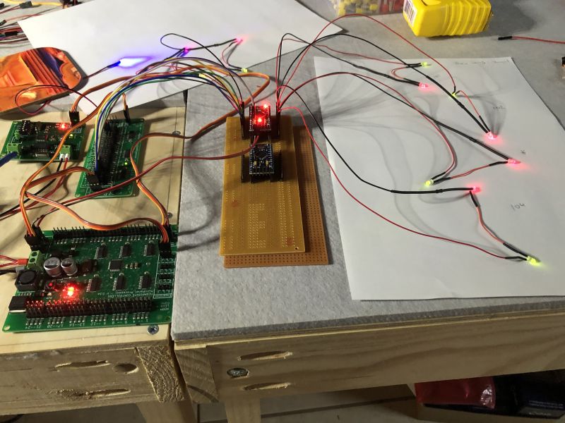
This last picture is a close up of the Arduino Pro Mini microprocessors that I am using to manage the bi colour, or composite led, colour change in response to the detected point position. I created the break out board myself. Once I have the remainder of the track and points established for this lower level, both boards will be in use driving 12 pairs of leds, one pair per point. It is also very handy that the MPP board has multiple 5V DC outputs, two of which will power the two Minis.
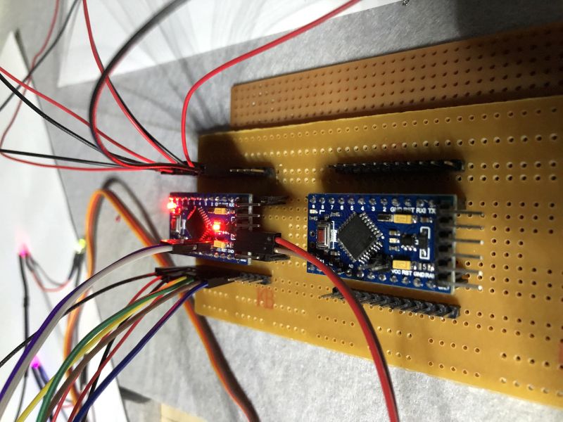
Sorry that all of the wiring looks a bit messy. Most of it will be managed and then hidden within the eventual mimic panel housing. I will not be finalising the panel its self until the track on this first level is finalised. (not quite sure what the fiddle yard will look like)
1 guest and 0 members have just viewed this.