Braughing to Standon branch design for N gauge
Posted
Full Member
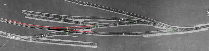
One thing I did want to be sure about and has been bugging me - primarily as I perhaps should know the answer already but still lack a tad of confidence amongst you experts - In the really helpful diagrams you've helped with there are various green marks which indicate where sections of track must be isolated in order the blocks of power to the track can be controlled for operational effectiveness.
The question - I assume these isolation 'greens' are in addition to the standard requirement for the two Insulated Rail Joiners after the frog of electro-frogs which must be there for polarity reasons when the point is thrown? I've tried to show what I mean with the superimposed point below with the IRJ's marked in yellow.

cheers
Paul

Posted
Full Member
The isolation greens ARE the Insulated Rail Joiners and the green is simply showing the positions of the Insulated Rail Joiners or at least the relative positions of those joiners. Where you see them on one side, that is the side you apply one joiner to while using a metal joiner on the unmarked side!
The actual position of the joiner is not an issue as long as it is in the vicinity of the area shown and on the same side of the rail.
If you are still stuck on this, take a photo of your actual layout as an aerial view and I can draw in the position of the joiners but you should follow what I meant in the first paragraph,
Cheers
Trevor
 Last edit: by xdford
Posted
Full Member
I have some other emails I have to attend to first but will post my homework shortly :-)
Paul
Posted
Full Member
West Station and sidings
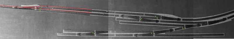
East Station and sidings - the assumptions being I can hold a branch passenger DMU in the bay road ..
cheers
Paul
Posted
Full Member
Paul
Posted
Full Member
You have fairly well nailed it so well done!!! I enlarged the picture so that it was easier to see and checked it against my original diagram for the West Station
However in the process of double checking both our works, I noticed two more slight errors on my part for the West Station so here they are -
a. There is no common feed to the siding between "K and "N" - fairly easily corrected
b. The common wire between "G" and "H" either needs to be removed or an IRJ placed on the common side at "H"
We have a fairly busy day but I will check the "East Station" in a while!
Again sorry about the goofs… you think you have something covered and there it is. Had you got to the testing stage as I outlined, I think you would have found it anyway but there you go!
Cheers
Trevor
Posted
Full Member
I'll check things out later today after work … and hopefully my BR Class 20 shunter will turn up later or tomorrow, then my locos (and DMU) will be complete.
Paul
Posted
Full Member
Thanks for the backup… appreciated!
At the moment I think there is no problem with the East Station wiring diagram ( I checked it again before starting to write this) but I will look at it again in a day or two and confirm that. About a month ago we had a leak in our roof that damaged a ceiling and while I was looking at the diagram this morning, we had the plasterers in so that casual glance without a pre-thought meant I saw it as was rather than how I thought it was!
Regardless of whether you went with DCC or blocks as we have, you still would have issues with wiring and insulators so I guess the question is, do you eventually want to go to DCC? There would be some rejigging needed with IRJ's etc but it is not impractical to alter the plans accordingly.
Anyway, for now good luck with it!
Cheers from Oz
Trevor
Posted
Full Member
I have gone over the East Station a couple of times (earlier this morning before work and just a few minutes ago circa 5:30 after work) and unlike the West side, I cannot see any problems arising with the wiring… yet.
However I invite a check and anything unforeseen will show itself when you do the electrical testing or if anyone else wants to point out anything glaring, they are most welcome to!
I have only one "concern" and that is the "Head shunt" for the yard on the track I marked "14"… is it long enough for you to put in a reasonable rake of wagons? It looks long enough in the original "from the air" views but the aerial shots make it look quite short! Does the layout go further east than it looks?
Hope the questions are not impeding your progress
Regards
Trevor
Posted
Full Member
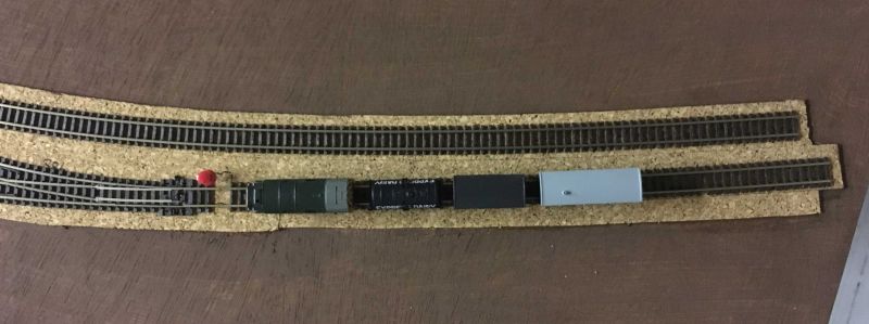

Lastly, stupid Easter question … using the photo below of the same point indicated on the diagram insert for IRJ's, I assume I simply use them here where indicated in yellow and green … or even further along to the left if I so wished as they will be performing isolation for the blocks 4 & 6? Also, is there still a need to connect the live frog (marked in red) to the motor point for purposes of polarity?

All regards
Paul
Posted
Full Member
I did not actually indicate that the frog needs to be connected but the rail on the "south side" does. I am not quite sure why you need to electrify the frog with a backup contact in the point motor as should function OK with the contact through the blade of the switch point but there is also no reason not to if that is what you are comfortable with. The IRJ's as you have shown them are in the right position for that point… well done again!
Personally I have only ever used a couple of point motors and currently do not have them although I am tempted with a relatively new installation to dig out the motors I do have. However for the far reach areas of the layout I do use mechanical point rods and I have never had an issue over 20 plus years.
On my diagram of Feb 24, I used the last switch on the local switchboard to feed in past the point at "D" which I then used as an isolating point for the leads to section "9" which you might wish to change by …
a) adding another DPDT switch to control section "9" and…
b) adding another pair of IRJ's at "H" between "H" and "G", one to each rail based on the diagram of Feb 24
That will be your call how you handle it, and no doubt some minor tweak will be needed,
Cheers and Happy Easter
Trevor
Posted
Full Member
I guess there will be varied opinion on the topic from other peers but I'll have a think about it and make a decision before getting to the serious track and point motor fixing stage.
cheers
Paul
Posted

Site staff
Paul, that is the main reason why modellers do power up the frog independent of blades contacting stock rails.Hi Trevor, thanks for the pointer re: 24 Feb diagram … I'll check this in more detail this evening. You are quite right - these is no need to connect up the V part of the frog so the whole frog has dedicated power via the point motor. the basic function of the point blade and rail live / common connections does a perfect job, only I've read on this and other forums that over time the track / blades get dirty, oxidised, etc and can make the smooth running of a slow loco problematic … so I was considering connecting up the V frogs now so I would not have to bother at some point in the future although equally I may never run into problems if I'm meticulous in my track cleaning regime.
I guess there will be varied opinion on the topic from other peers but I'll have a think about it and make a decision before getting to the serious track and point motor fixing stage.
cheers
Paul
The new Peco 00 Bullhead points already have the blades hard wired to stock rails & the frog - Unifrog - is completed isolated allowing the user to wire it up if required. This concept has been in use with their H0n & Code 83 line for a while now & it is guessed by some in the UK that as Peco updates existing turnouts, they too will become Unifrog
Product information | thehobbyshop
Ron
NCE DCC ; 00 scale UK outline.
NCE DCC ; 00 scale UK outline.
Posted
Full Member
You are using prudence to provide for future events with the cleaning. I am dealing with HO so I have a bit more space to deal with cleaning (and I do not have to that often especially now I am inside the main house) but thinking about it, for the want of a couple of minutes work, you will increase your overall reliability and not have the issue of cleaning apart from the track/wheel contact surfaces of course, so if you are prepared to do it, go for it!
Cheers
Trevor
Edited Note,
PS Looks like Ron beat me to it! Wonder if Peco will apply the same principle to their N scale points?
Cheers
Last edit: by xdford
Posted
Full Member
Posted
Full Member
Been busy soldering all my power droppers which is going well … and now getting close to the stage where I want to start planning wiring up the SEEP point motors. Based on the last few replies above where Sol and Trevor were discussing with me on livening up the V on the Electrofrog points based on throwing the point switch … I'm now a little concerned that on N gauge code 55 streamline turnouts this is going to be pretty tricky with so little space to actually solder the wire to the track (either the side of the track or the underside).
You can see what I mean with the limited space in the pics below. I'm clear on how to connect everything up but can really only find examples of O gauge turnouts being soldered on YouTube and not code 55.

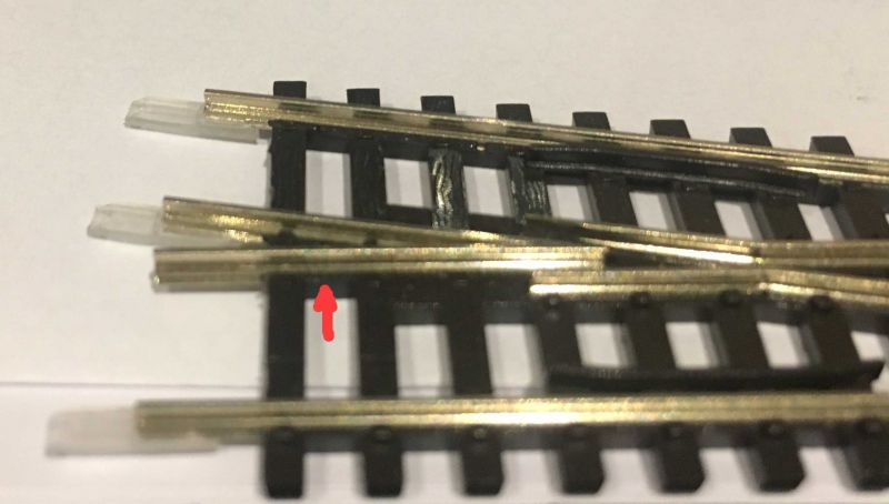
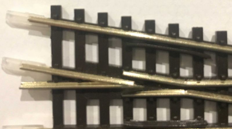
I can imagine the only place to solder a live wire is at the point indicated with the red arrow in the 2nd pic above, either to the outside of the track or underneath - any other thoughts please … or even better a link to a video where is actually demonstrating this for code 55 turnouts?
cheers
Paul
Posted
Full Member
These are electrofrog points so the connection point for the wire does not need to be (in the way you have drawn) west of the frog, Location of the wire does not strictly speaking matter.
You can connect your wire for the frog…
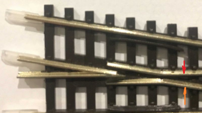
Either the red or the orange connection point will do with the feed wire on the outside of the rail,
Hope this helps
Trevor
Last edit: by xdford
Posted
Full Member
Posted
Full Member
I must have been suffering from a bit of heat stroke in this autumn weather here too, having put East instead of West - now corrected! Easy enough not to think in terms of electrical feedback.
In the interests of this forum helping others, how is the testing going? Have you developed any techniques apart from the ones we dealt with that have helped? Any major hurdles crop up or major goofs been found? Have you been operating with the trains or still in the disciplined building stages?
Cheers for now,
Trevor
Posted
Full Member
Still in the disciplined stages of testing and soldering power / common drop wires and this week the power feed to all points ready for connecting up to SEEP switches - basically been taking my time to try and develop some sort of soldering technique but with the Hakko soldering station it makes things soooo much easier.
Firstly, I performed testing on the West station areas (modules 1 & 2) with all the tracked connected with metal rail joiners and isolating plastic ones as per the plan. With them connected physically I set about creating a mini bus, if you will, using 12 pin electrical connector - half looped for 6 common feeds and half looped for 6 live feeds (which could be multiplied up again using extra individual blocks (see image). The block was then connected to the Gaugemaster. Each length of red or black wire (approx 3ft in length) had a crocodile clip connected at the end - all wire used will be reused at some point in the overall layout so nothing is wasted. Then I set about connecting each clip I needed to various parts of the track to mimic all the connections on the electrical plan you helped me design - this meant I could clip them on or off at will to also mimic isolating various parts (in some cases I had to stop the train and move the clip around to allow the train to continue). Overall it served its purpose and all the connections worked fine and the operation was as I had intended - only found one small part of track not connected which was an oversight on my part at the module joins. So in essence I used your idea but tweaked it a little - also means I can repeat the same thing for the East end modules in due course.

As I write I have just completed soldering the last point live feed wire and now beginning the drilling of holes in the baseboard for the droppers and point feeds … then pin down the track in place - I plan to fix the track down more solidly with the adhesive used when ballasting.
So far , so good
Paul
1 guest and 0 members have just viewed this.