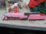
LNER 06 (Being built from an MOK 8F Kit)
Posted
#232667
(In Topic #12743)

Full Member
The resurrection of a long time inhabitant of the workbench
A Happy New Year to all.]First a bit of background, about 8 years ago my good lady became ill and had to give up work. She was fortunate in that she was able to take redundancy and she spent some her redundancy money on a kit for me. I chose the MOK 8F - MOK = Modern Outline Kits available from here MOK
I wanted the 8F to build as one of the locos that were ordered by the LNER during the war. My initial plan was to build one of the examples built by the Southern Railway for the LNER but further research since has changed that to become one of those built by the LNER at Darlington. You might ask why - because I wanted a riveted tender and I had already bought spoked wheels.
The ones built by the Southern had welded (smooth sided) tenders and most of the LNER built examples had solid wheels as on the tenders of the A3/4's but at least a couple of the Darlington examples had spoked wheels to go with the riveted tender. So mine will now be either 3135 or 3144
Rather embarrassingly I started it around 6 years or more ago and never got anywhere near finishing it. About 18 months ago I had a second bash but still didn't even get the tender finished. Chris has been pointedly asking most of this year when I am going to finish it and I had planned to return to it when I got distracted by the J79 in October. So I made the promise that I would return to it over Christmas and endeavour to get it completed.
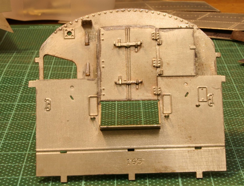
I thought I would ease back into it with something easy, or so I thought. I started on detailing the backhead.
These are some of the many parts that make it up.

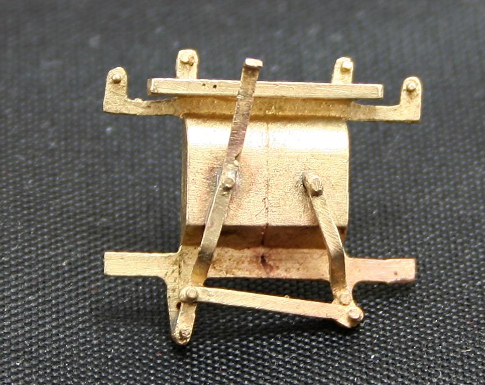
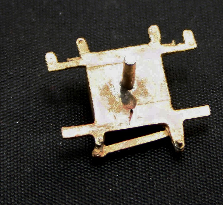
I had to make this up from a couple of pieces and I drilled and soldered a spigot to the back to make it easier to attach to the backhead itself.
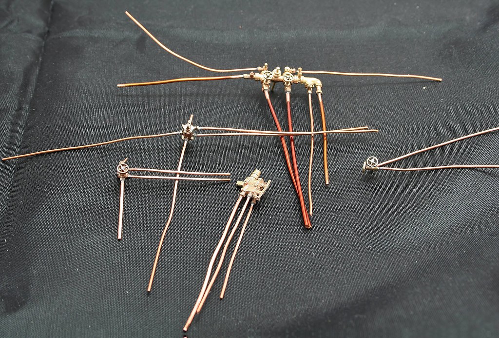
Then the myriad of spaghetti that will be the pipework.
Having shared Nick Dunhill's masterpiece a few weeks back I was keen to replicate the gauge glasses that he did. On this particular backhead this entailed cutting off the levers, and then cutting out the rectangle of brass to insert the square perspex later in the build and then reattaching the levers to the sides.
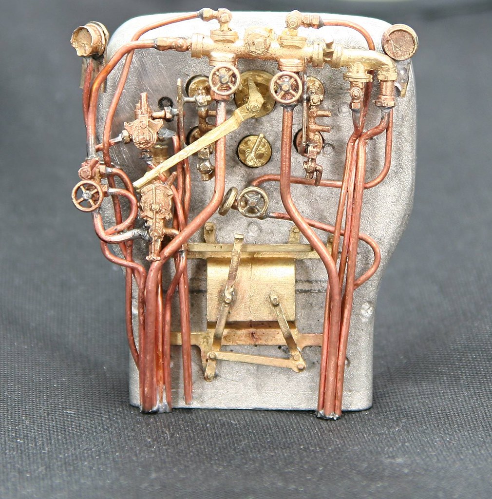
These are the almost finished article that has taken just over a week to put together. - Most of the parts are removable to allow the backhead to be painted.
Because there are a few much better builds than mine on the forum I am not going to go into the level of detail that I might do normally but just show the key stages as I complete them - the main goal is to get it finished.
Regards Rob

Posted
Full Member
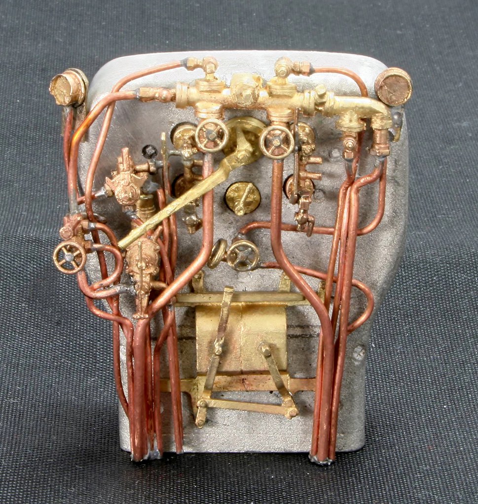
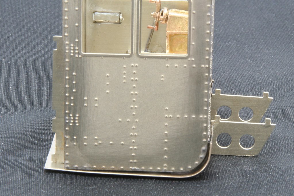
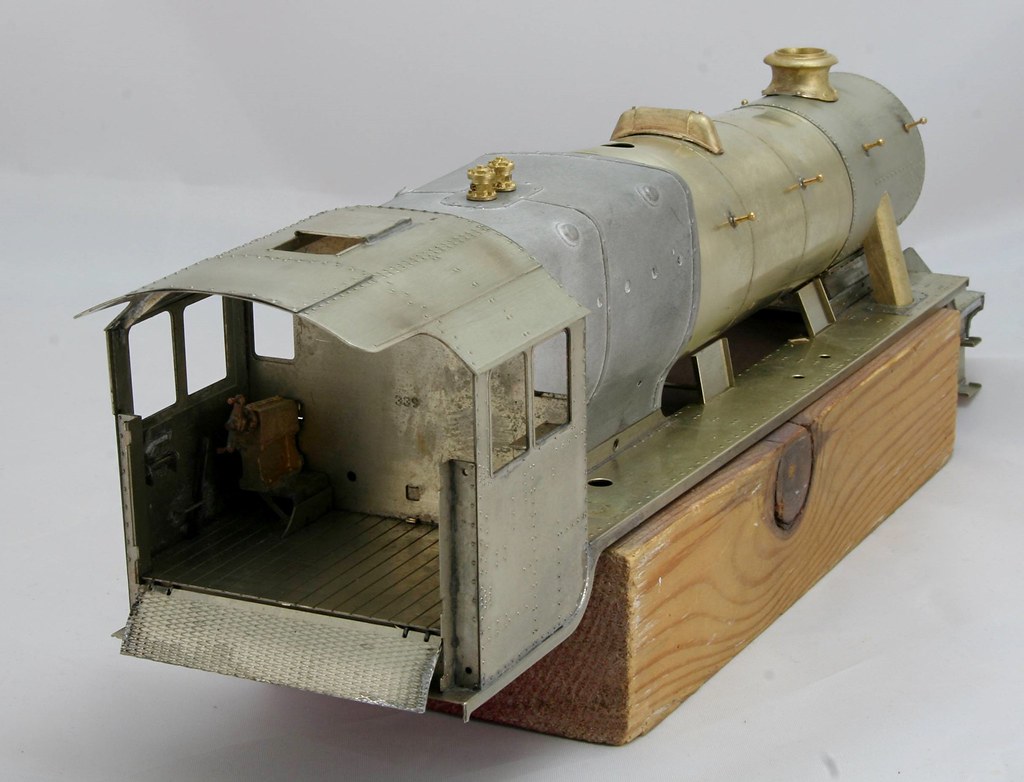
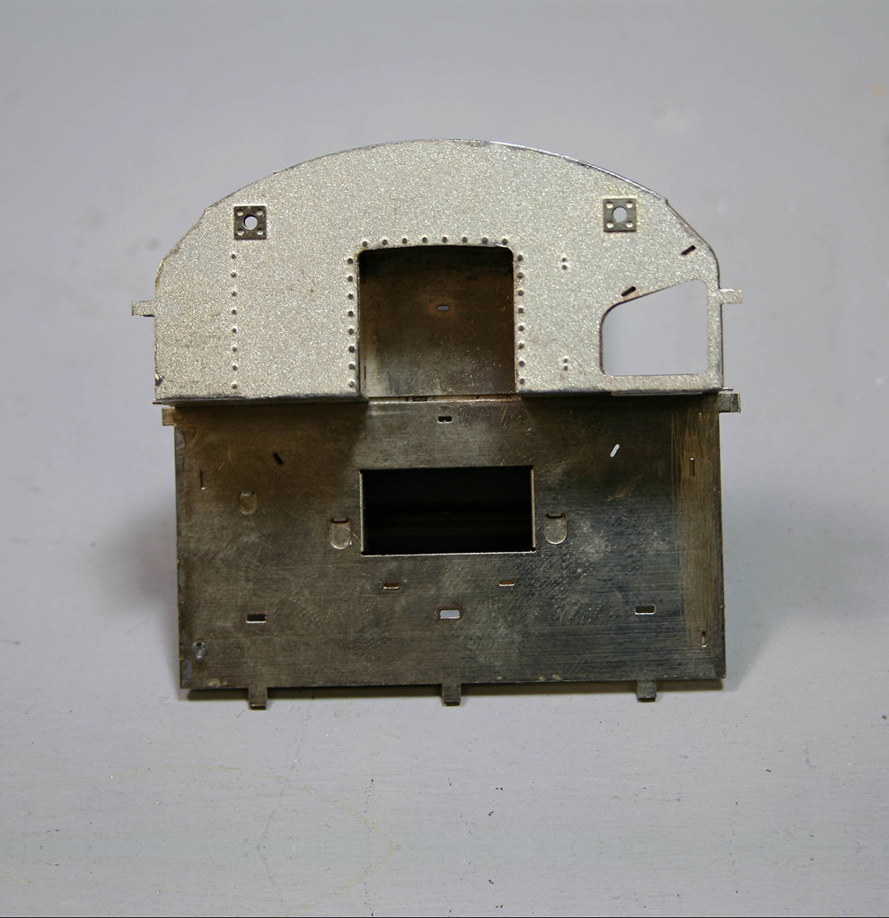
I am having a little more one step forward and two back with this build and it’s my own silly fault. In my eagerness to crack on I hadn’t noticed a photo in the Wild Swan LMS Loco profiles book on the 8F’s that shows the inside of the cab and more importantly the backhead. It seems that I have too much pipe work for my period so some of it needs to come off again.
I am thanking myself in that I took the extra time and effort to make most of the parts removable because that will make redoing it much easier.
This shows how the parts are removable

Below is a crop of the cab photo in the Wild Swan book. The photo is credited to the National Railway Museum and is used here purely to illustrate the differences between what I have done and what I should have done.

Regards Rob
Posted

Full Member
 Now you've got me trying to spot the difference.
John
John
Posted
Full Member
It's mostly the pipes at the right hand side. Some need removing and some need directing elsewhere.
Regards Rob
Posted

Full Member
More patience than me, I'd just throw some sauce on it.
Nigel
©Nigel C. Phillips
Posted
Full Member
The boiler comes pre rolled and according to the instructions so does the smokebox inner but mine wasn't. That wasn't an issue and I soon had it rolled.
Now for the 'I'm a dummy' bit, the instructions are quite explicit about using two of the formers for the x71 and x72 (sorry I can't remember if the preceding number is 1 or 3). Leaving x70 to go in the smaller end of the boiler. Because they all look identical (but aren't Grrr) I managed to pick up the wrong one and only discovered my error when I had it all nicely soldered together.
My only saving grace was that I discovered the error (part x70 is slightly bigger than x71/x72) before I soldered the other wrong bit (x70) into the smokebox). At 11:15 on Tuesday night I didn't have the headspace to sort it out so I went to bed.
This morning I set to and using a pointed scalpel and gentle heat from the micro flame I slowly worked my way around easing the boiler away from the former with regular quenching to take it out and replace it with part x70.
Thankfully I got away with it, in part I think due to the fact that I had soldered it in initially using the microflame to chase around a tiny amount of solder which meant that although it was held very securely it was easy to break the bond from the thin layer of solder.
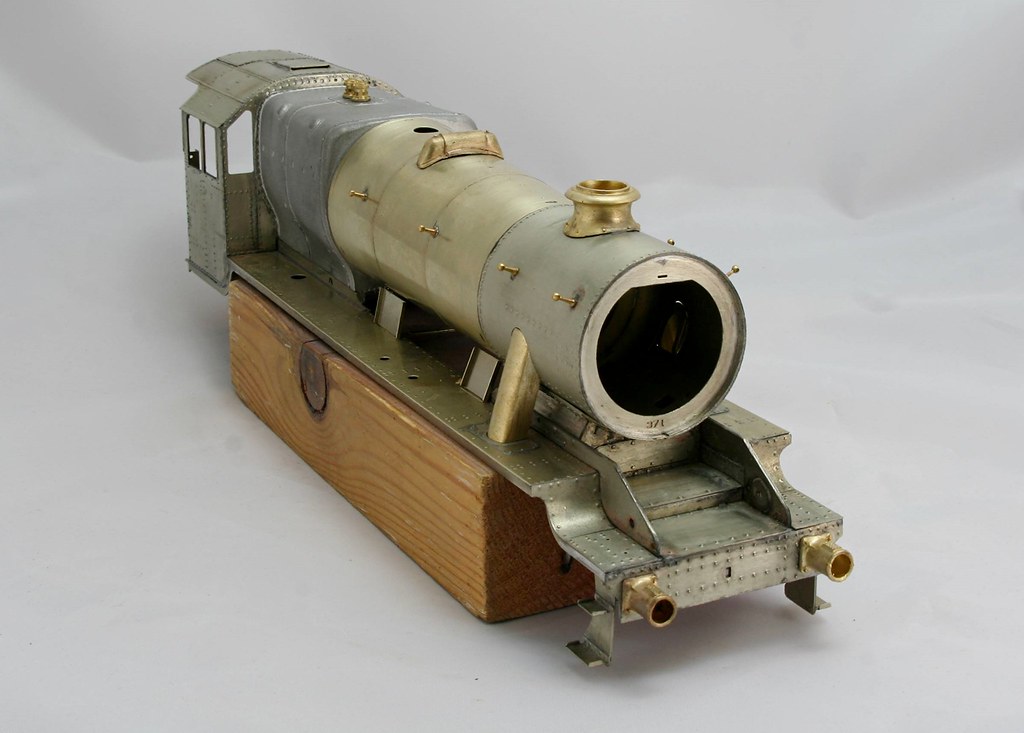
This is the boiler and smokebox assembly after my recovery.
Those with sharp eyes will not the piece of scrap protruding from the front of the smokebox.
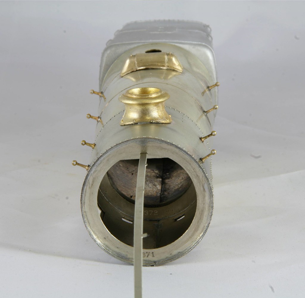
There is a clever bit of the etch designed to ensure that you get everything lined up by inserting a piece of scrap into a slot etched into each of the three forward formers

data-redactor="1"I left it longer than suggested and used it to view down through all the apertures in the boiler top. In fact I left it in place as I soldered on the castings on top of the boiler. To solder these cleanly I flattened a couple of small bit's of 145 solder in some pliers, placed them either side of the chimney opening after using a taper broach to open the hole up to take the spigot from the casting as tightish fit. a squirt of flux and then I place the chimney on top ensuring that it was square I heated the casting with the microflame until the solder melted allowing the casting to sink into place. - Repeated for the next casting (which I have to be honest and say I have no idea of the name or purpose of it).
At this point the Firebox, boiler and smoke box are all a nice tight push fit I won't make it more permanent until I am happy with everything.
Finally, I had fitted the cab roof on Tuesday but I still need to sort out the subframe under the floor.
 Last edit: by Rob Pulham
Regards Rob
Posted
Full Member
Looks brilliant Rob :thumbs
Terry
Posted
Full Member
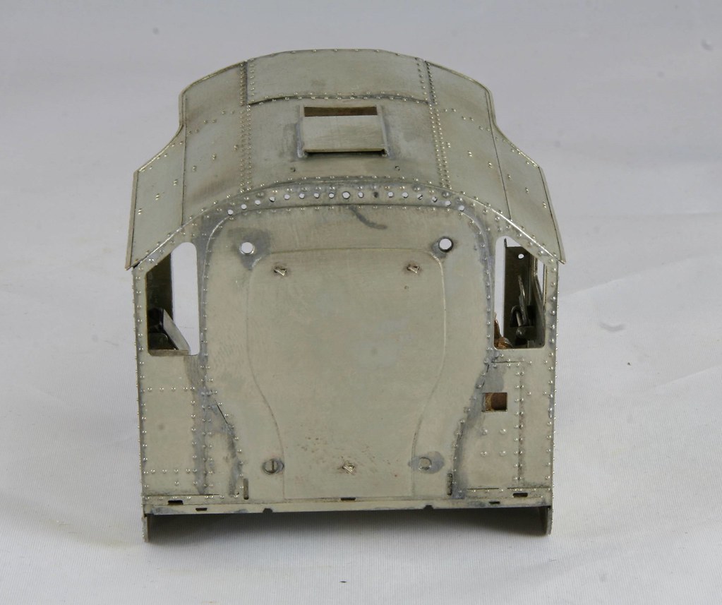
Mine was a little more fundamental - the curve of the footplate under the cab was not anything like the curve of the cab sides
Because I didn't have the benefit of the updated instructions that Mark kindly shared with me after and enquiry over on Western Thunder (I have emailed Dave Sharp to ask for a set of the updated instructions) I had previously added the cab front overlays and soldered all around the seams. This meant that tucking the front of the curved section up under the top layer of the cab front as advised in the updated instructions wasn't to my mind - I worked on the theory that if I tried to remove the thin overlay I would irreparably damage it.
That left the alternative which was cut/file the front section down so that it sits just below the footplate rather than tucked in behind the front plate and to desolder and file down the sub frames until the curve better matched that of the sides of the cab.

As you are looking at it, it took two goes at desoldering, filing down, before resoldering to test the fit for the left hand subframe and six goes for the right hand subframe. At each desoldering I carefully cleaned up before filing a little more off. You may wonder why I resoldered at each test, it was because I couldn't hold it in close enough proximity to accurately check the fit when trying to hold all the parts while they were
I have to say that had I continued with the build to this point when I started back in 2011 or so, I would never have had the confidence to desolder and resolder the same part so many times to get the fit that I wanted. I would never have been happy with it either.
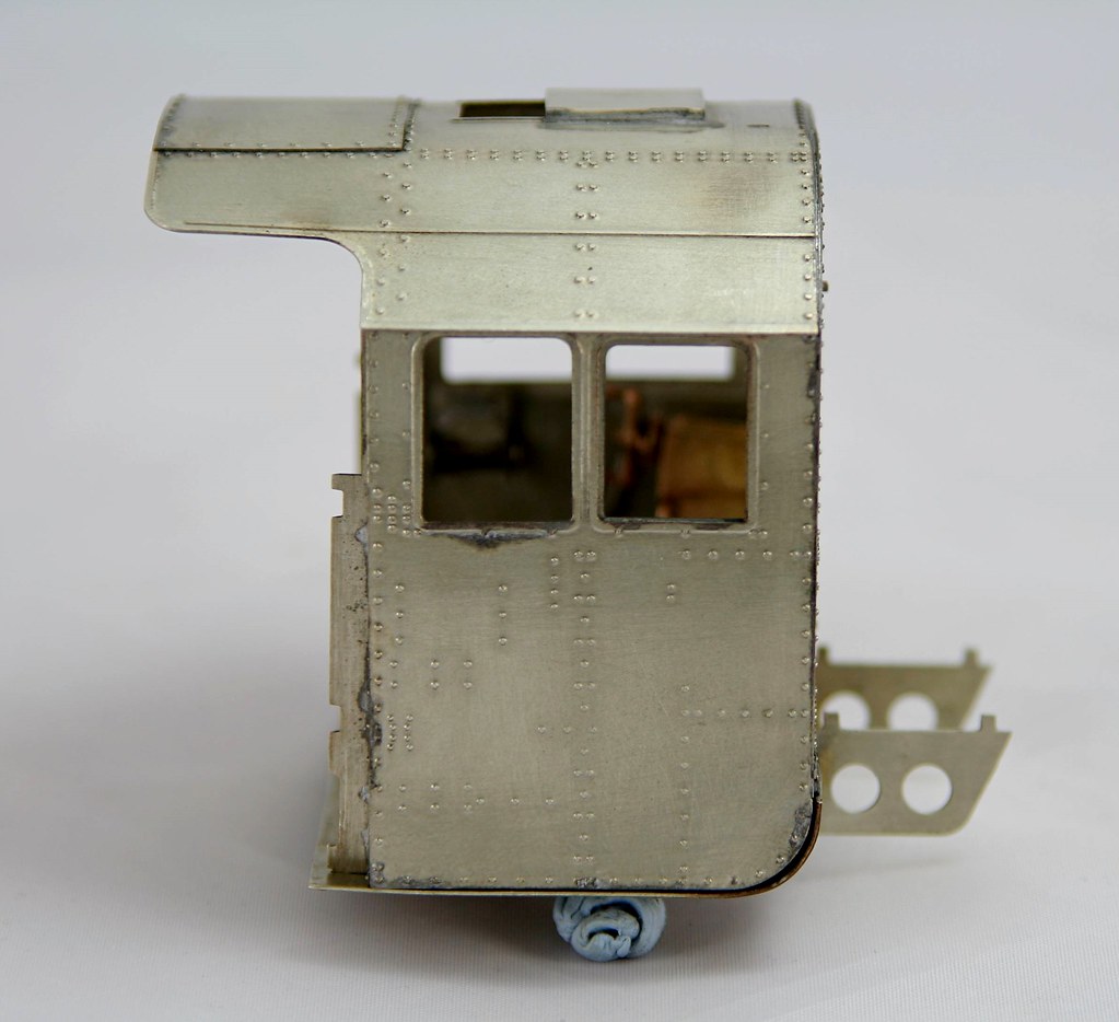

The slight gap on the right hand in this view will close up when I solder it all in but I am triple checking all is right before taking the final step.
Regards Rob
Posted
Full Member
7th hole from the right. (Where there are wivets count 'em).
Superb modeling.
Nigel
©Nigel C. Phillips
Posted
Full Member
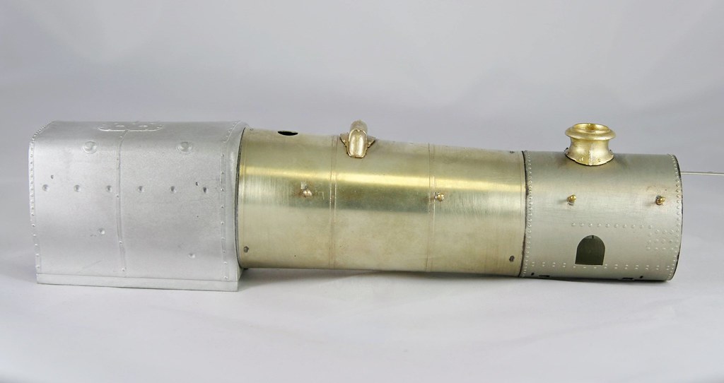
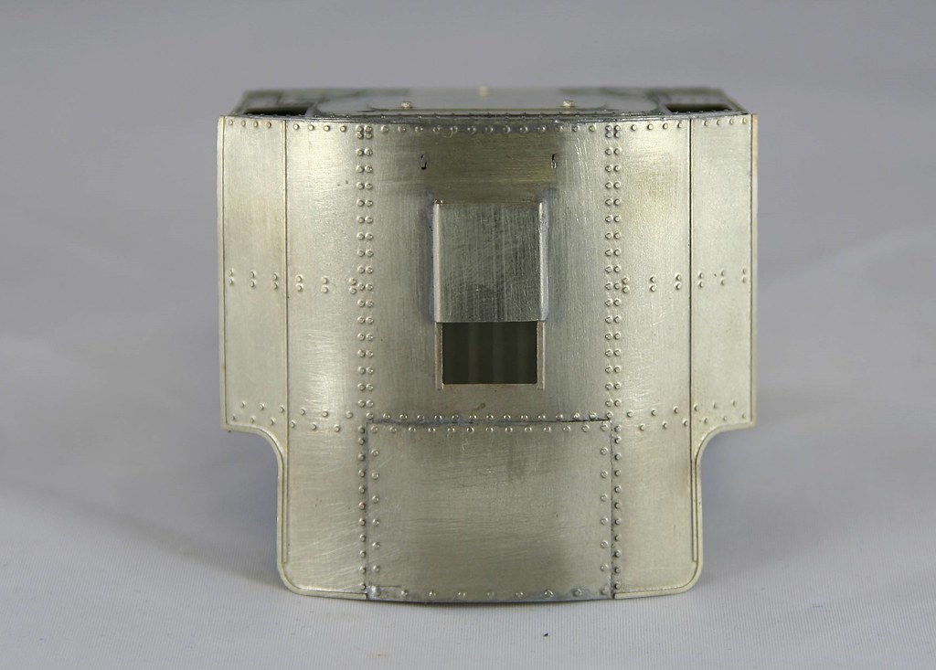
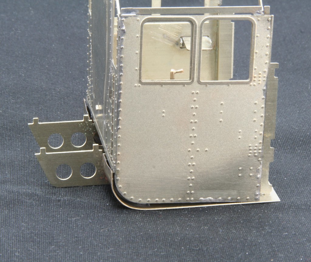
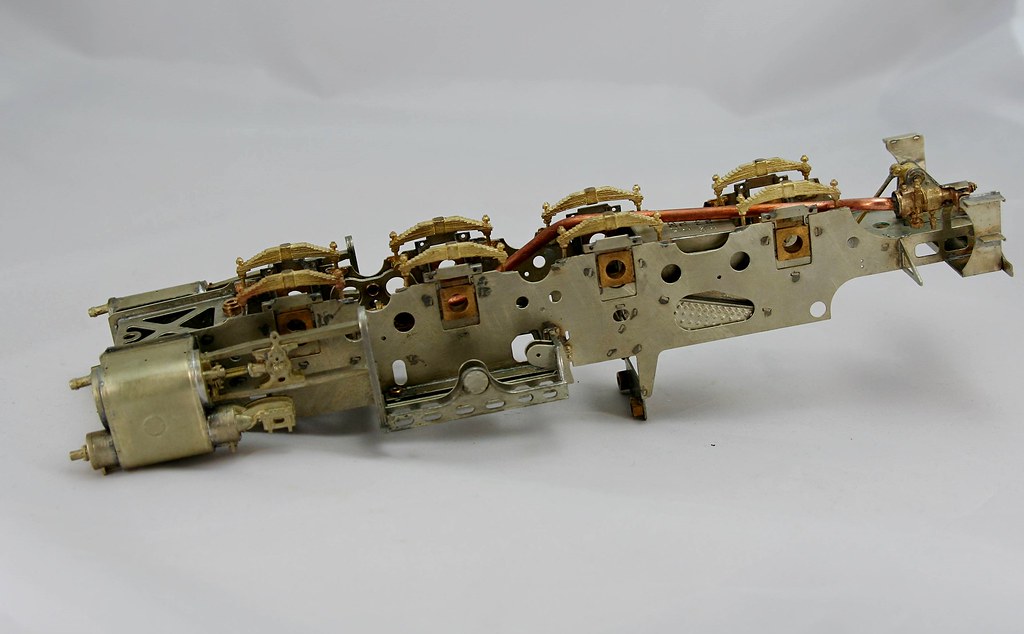
Further work over the weekend has seen it start to look like a loco at long last.
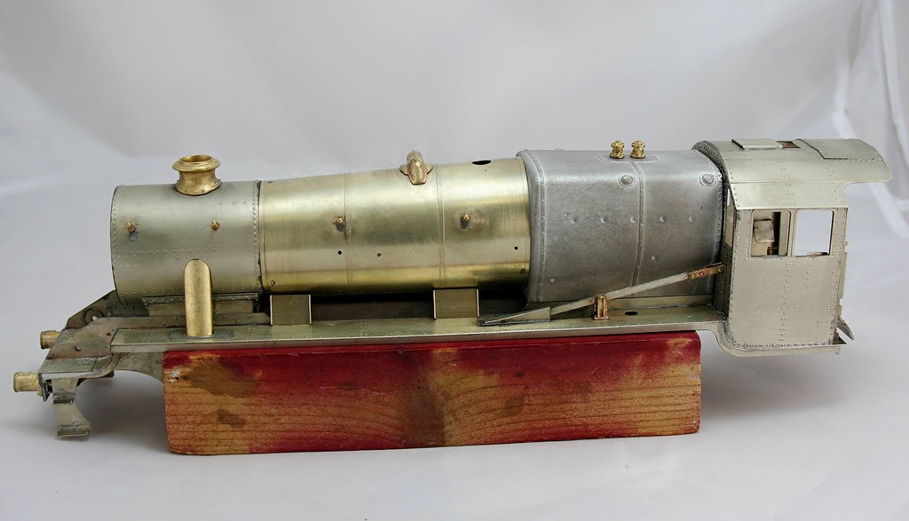
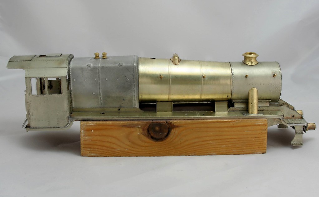
At the moment all except the cab, the reversing lever and it's housing are just sat in place and are held by the firm fit of the components. - The sand shields are just lent in place because I need to drill them yet for the sandbox fillers. I am slightly surprised that they don't have at least some semblance of a hole etched in them given how well everything else is portrayed.
I also need to drill and put a self tapper in the top of the cab face of the firebox to close up the very slight gap on the drivers side before I solder it in place. The instructions suggest doing this but I thought that I had got away without the need until I put everything in place.
Regards Rob
Posted
Full Member
John
John
Posted
Full Member
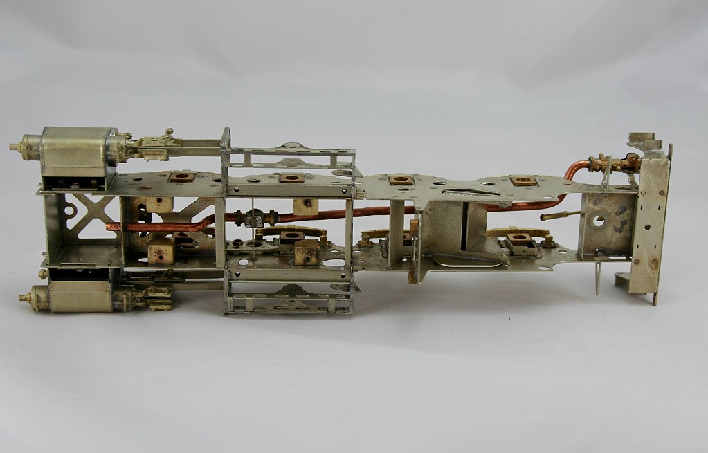
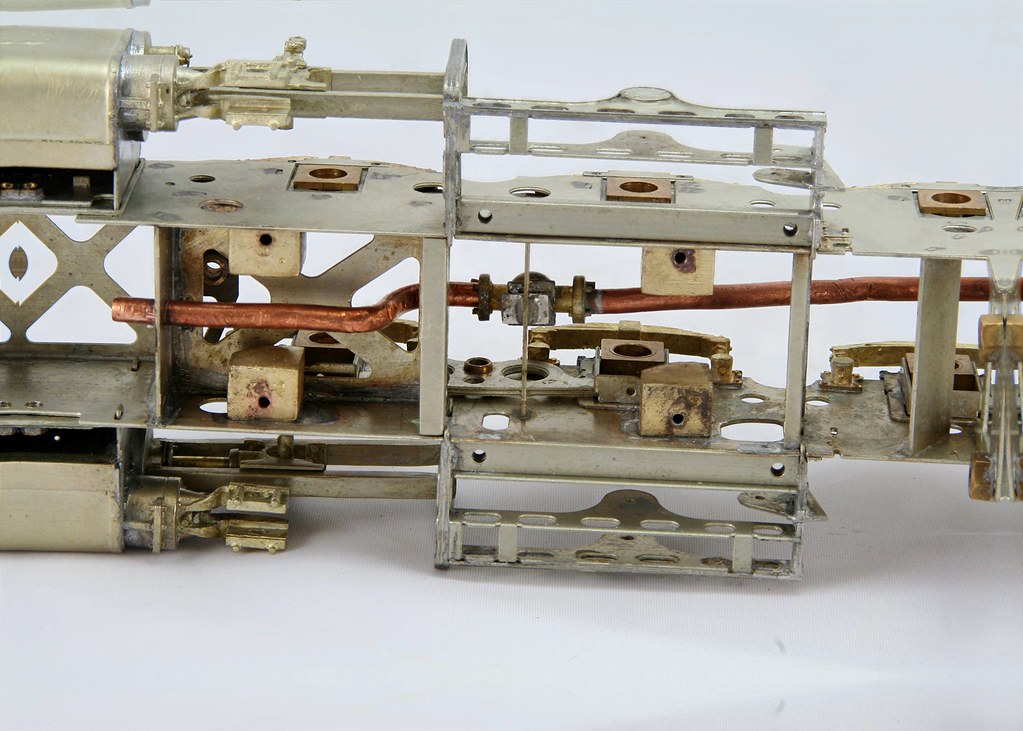
Partially this was where it was until I returned to it last night. The idea being to get the chassis up and running now before I solder all boiler etc. in place just in case I need to make adjustments to the footplate.
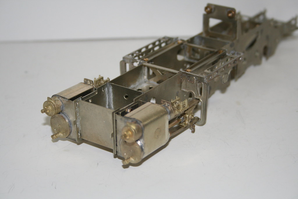
Last night I added stops to the bottom of the horn guides to retain the bearings, resoldered the the top part of the cylinder wrappers which I obviously hadn't done a very good job of initially, and then I started modifying the loco springs to fit - if you are making the chassis compensated you need to take some off of the spring hangers to accommodate movement of the rocking beams. - not really much worth taking photos of yet.
Regards Rob
Posted
Full Member
Regards Rob
Posted
Full Member
John
John
Posted
Full Member
Me too John, it is a concern I must admit. - I had big plans to crack on with it today because I had a rare Sunday adjacent to my soldering iron but I have spent most of the day looking at nonsense on the internet due to a complete loss of mojo.That is an amazing build Rob. Hope you've done your sums and that the pipe won't foul the mechanicals.
John
Regards Rob
Posted
Full Member
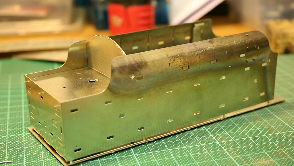
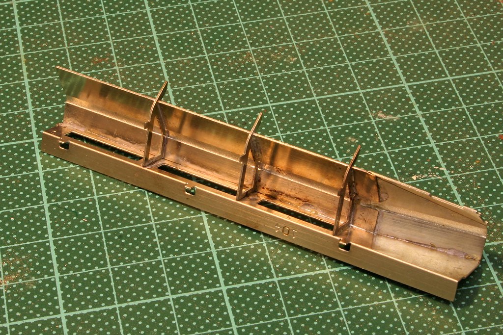
Shaping the curves of the inner tender sides was interesting because in my ignorance I had chopped off one end of the etch which contained the marked
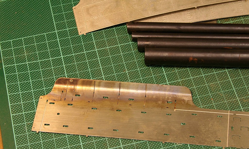
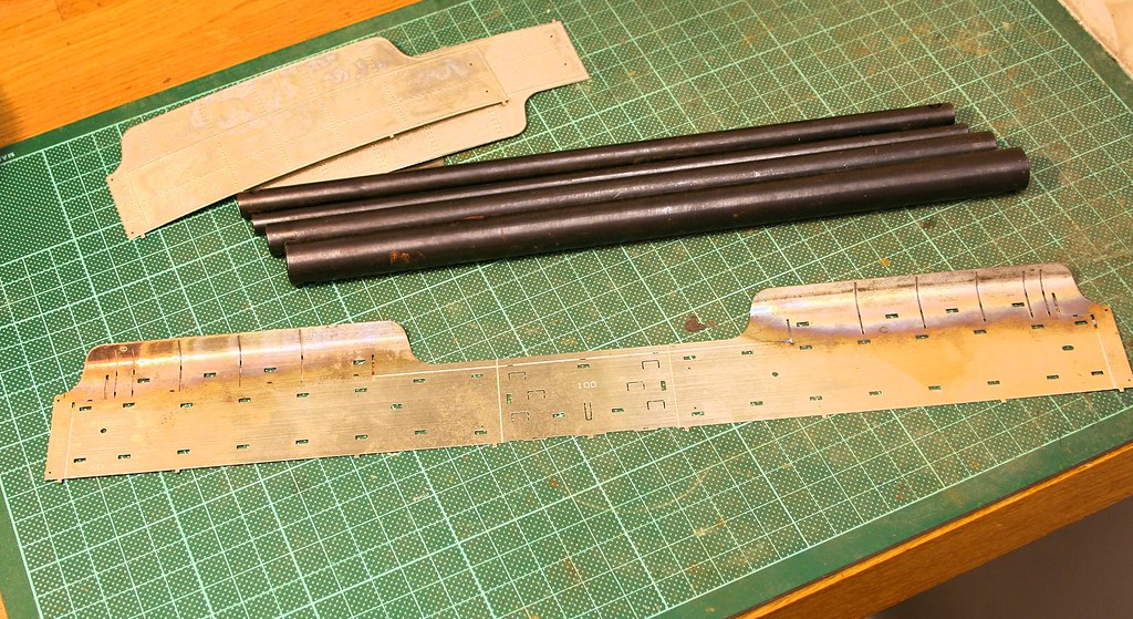
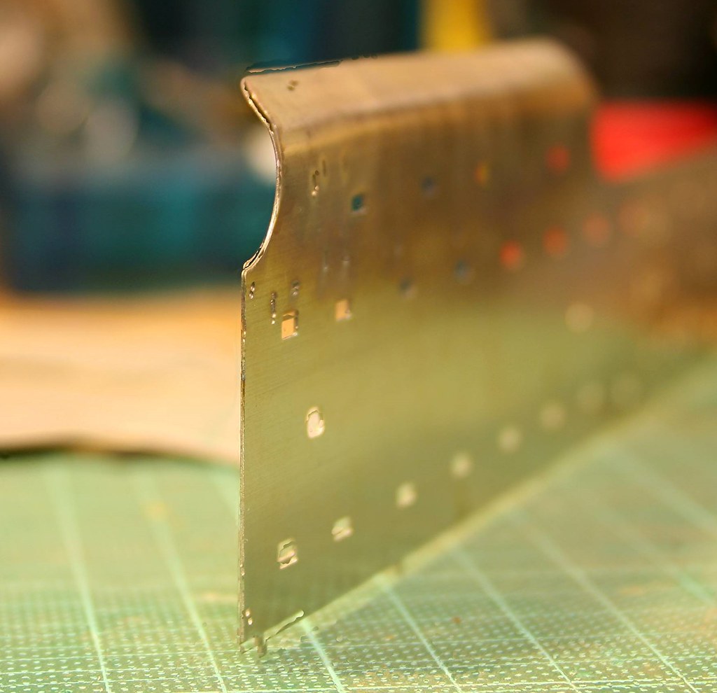
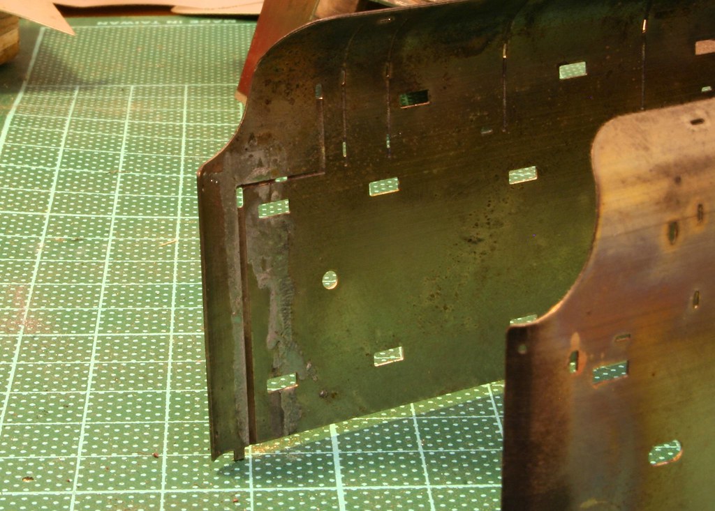
In order to bend the front curves of the tender sides which were very close to the half etched line for the location of the front bulkhead I soldered in a couple of strips of scrap to stop it bending on the half etched line instead of where I wanted it to. Once happy I soldered in the rear bulkhead and started to add details.
Last edit: by Rob Pulham
Regards Rob
Posted
Legacy Member
reg
Posted
Full Member
The quality of the kit is superb, sadly it's let down by poor instructions. In fairness I believe that they have been updated since I bought mine - it's been on the bench intermittently for a few years….
Regards Rob
Posted

Full Member
Posted
Full Member
Before going any further I started to make up the bulkheads which are made up from multiple layers. Here the instructions (or my interpretation of them) let me down again and I managed to get the overlay for the top of the front bulkhead out of sequence meaning that I had to cut a section out of it to prevent having to undo a lot of work meaning that it sits around the lockers not behind them (it was quite easy to do with scissors due to it being half etched). It isn't visible in the end result but I know I had to do it.
Front Bulkhead
Fire Iron Tunnel

Regards Rob
1 guest and 0 members have just viewed this.