LMS Pull Push Coaches
Posted
#179269
(In Topic #10141)

Full Member
Finally!
Well, we've waited and waited but there is no sign that any of the manufacturers will ever produce a model of these. Even if they started today, it would be the best part of two years before we saw anything. I have decided to take the bull by the horns and do a pair of two coach rakes myself.My chosen prototypes are Diagram (D) 1790 driving trailers paired with D1784 all third. My driving trailer kit is actually a D1735 3rd brake but just as in the prototype will be converted to a driving trailer. These were period II coaches, built around 1930.
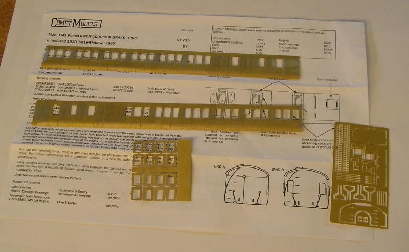
I unpacked a kit to illustrate the contents:
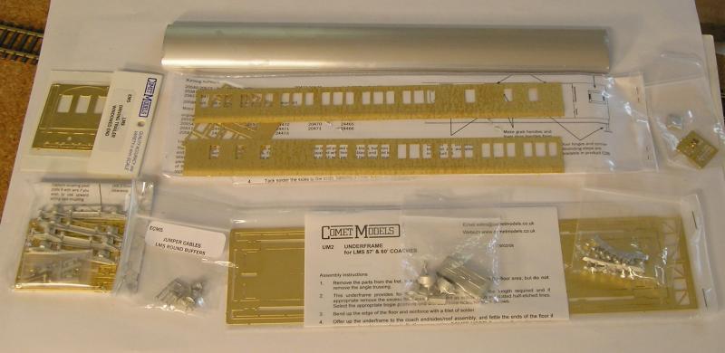
Comet kits are modular and consist of packs that can be purchased individually. You can see each pack has its' own instruction sheet.
At the top is a extruded aluminum roof. Below that are the etched sides and below that is the etched underframe.
To the left is the end pack that I need to convert to a driving trailer. Below that is a pair of bogies consisting of etched structure and cosmetic whitemetal sides.
There's a pack of buffers and jumper cables, a pack of underframe castings and roof ventilators.
Pricewise these are typically around 45.00, not too far off recent RTR offerings, although they do have to built.
The excitement builds!
John
 Last edit: by Brossard
John

Posted

Full Member
Good luck with building your Comet Push Pull coach, they certainly make lovely models even though they are a little on the pricey side.
I gave up waiting for a R.T.R. Push Pull set from the manufacturers and ended up converting 2 of the old Tri-ang and an early Graham Farish Suburban Brake Second Coaches with quite pleasing results.
I look forward to seeing the finished model in due course.
John.

From the site of the 'Great Train Robbery'!
Posted
Legacy Member
reg
Posted
Full Member
So, I made a start this morning, with the bogies:
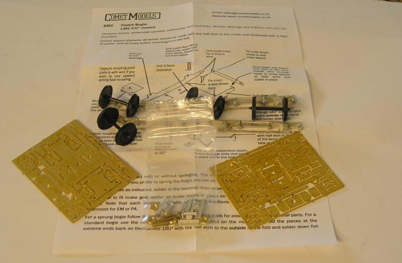
I started by cleaning up the mould lines on the sides with a fine file. I also straightened the bar between the W irons. The back were rubbed on a medium file to smooth them down.
Wheels are Gibson 14mm (3' 6") dia from Mainly Trains (great service btw). If you were to build this in 00, you wouldn't go far wrong using Bachmann (which regular readers will know I use a lot, albeit modified) or even Hornby. These can be bought separately.
You need pinpoint bearings which are usually not included. These can be obtained from Mainly Trains too. For this I will use the flanged type.
John
Last edit: by Brossard
John
Posted
Full Member
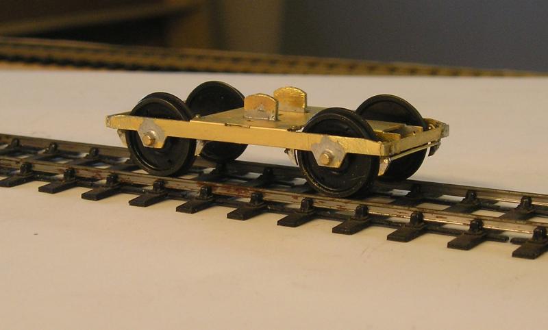
It always take me a bit of time to get my head around the designer's intent. I expect the next bogie will go quicker.
This is a "standard" bogie, ie rigid. There's an addon you can get for springing.
John
Last edit: by Brossard
John
Posted
Legacy Member
reg
Posted
Full Member

The bogie is a very rigid structure now and I had to file away the bearing flanges and also file a notch in the bearing to get the wheel pinpoints to go in.
Now that the wheels are in, they do roll freely so I'm happy with that.
I am NOT happy with that bar between the W irons. They bend if you look at them. I can see them being replaced by metal.
John
Last edit: by Brossard
John
Posted
Full Member
Testing shows that the bogies need shimming. The underframe is straightforward with no particular challenges.
John
Last edit: by Brossard
John
Posted
Full Member
Next, I soldered a piece of scrap brass sheet over the bogie fixing hole and drilled that.
I then re-assembled the bogies and fitted them. Voila! The coach runs freely through the test turnout now.
Finally, I thought that having the captive nut on the bottom of the bogie (as the instructions call for) didn't make sense to me. If the bogies need to be removed after the coach is built it would mean that the coach would need to be disassembled. So, I removed the nut and resoldered it to the inside of the underframe.
I thought that, before going any further, I'd better look to the body of the coach. I got out the sides pack:
The pack comes with the sides and droplights for the doors. There's also a pack for the ends that I won't be using for this model.
To the right is a useful thing to have that is not included in the kit - the super detail pack, C26. I got it for the hinges, but there are other useful things as well. I can't imagine not doing the hinges, although positioning them correctly is going to be tricky despite the included jig.
The instructions are available at Comet Models' site and can be viewed or downloaded. There are also a number of useful downloads for the modeler.
John
Last edit: by Brossard
John
Posted
Full Member
I thought I'd do a tutorial in case anyone is tempted to build a Comet kit.

I mentioned that the detailing pack contains a jig. You can see this on the upper coach side. I used the jig to carefully mark the holes at the doors on the ends. Next I used the marker to make black lines along the length of the sides as you can see.
I used the scriber and the steel rule to scribe a fine line between the marks I just made. Now having a good datum in the horizontal and vertical (doors are half etched) I used the jig again to mark the locations of the hinge holes. The horizontal line lets you ensure that you have the drill (pictured above with a 0.020" bit) positioned precisely.
By marking the hole positions, if you make a mistake, you can correct. Trying to drill a new hole close to an old one is next to impossible.
Once the holes have been marked, you can now complete the drilling of the holes.
There will be raised material on the back of the coach so I used the riffler file to smooth that down. Finally, use a fiberglass pencil to rub off the black marker as you can see on the lower side.
I am mystified as to why the hinge holes are not half etched like the other holes for door bangers, grab and door handles.
John
Last edit: by Brossard
John
Posted
Full Member
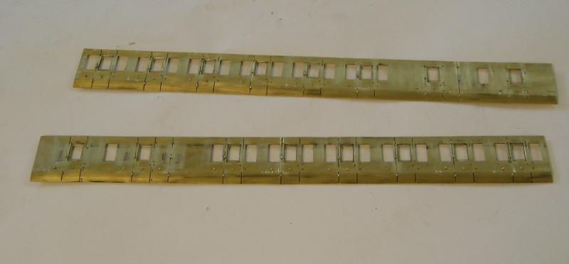
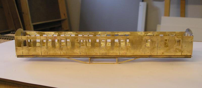
You can see the droplights in the doors. Those hinges are TINY! I can't even feel them on my finger. I used angled tweezers to grab each hinge and dropped it in the hole. A small file was used to hold the hinge in place while I soldered the back. There are 54 hinges. :shock:
Door bangers were easy if tedious. I soldered 0.020" brass wire at the back and filed it to about the right height. You don't even want to see the backs of these sides, what a mess! They have been given a good scrub up. I'll probably run a grinding wheel over the backs to smooth things down a bit.
The door and grab handles will wait until I've painted and lined the sides.
John
Last edit: by Brossard
John
Posted
Legacy Member
reg
Posted

Inactive Member
Max
Port Elderley
Port Elderley
Posted
Full Member
I realised, as I was looking at the kit, that this a period II vehicle, built around 1930, before simplified lining was introduced (in 1934). That being so, it will require faux panel lining in the Midland style :shock:. All period I and II coaches were decorated like this and even the first lots of period III (introduced in 1932). The only way a period I or II coach would get simplified lining would be if it was shopped for work that included a full repaint.
I've never seen a picture of a period I or II coach in simplified lining and suspect there weren't many, if any. A great many period I coaches were converted to ambulances during the war.
John
John
Posted
Full Member
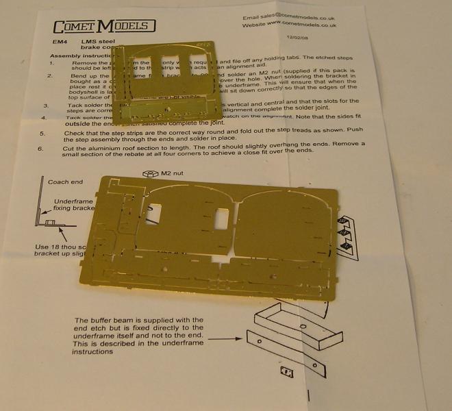
The kit comes with a brake end pack, bottom fret. I got the driving trailer end pack for this model, upper fret. Nothing particularly noteworthy here.

Here, the ends have been made up. There's a box at the bottom of each end with a nut soldered to the inside. Once the sides have been soldered to the ends, for which the underframe is used as a jig, the body will be screwed on.
John
Last edit: by Brossard
John
Posted
Full Member
How on earth does one fit a 3mm wide strip of flimsy brass to the solebar so that it is straight and a consistent distance between the flanges?
Here's how I approach it (learned from Comet on a previous underframe build, Mk1 I think). This underscores what I was saying about technique trumping skill.
The first step was to mark out some 0.040" plastic card for 0.020" holes. The holes are for wires that will support the step board. I did the marking out on the sheet and only after that did I cut it to a strip intending to be a snug fit between the solebar flanges. I did have to spend a fair bit of time shaving the width until it fit:

Here's the strip on the solebar with 0.020" holes drilled every inch or so. By doing this I can mark the holes to be drilled in the solebar in a straight line. The step board is not central on the solebar but a bit nearer the top. The holes must be drilled to allow for this.
The next step was to drill all the holes after using the jig to mark them on both sides. Drilling through full thickness brass is hard on the drill bit. The work goes quicker and easier if you dip the tip of the bit into some oil. I managed to drill all the holes without breaking the bit.
When you've drilled all the holes, insert wire (I used 0.45mm NS, but 0.020" brass will do as well), and solder into position:
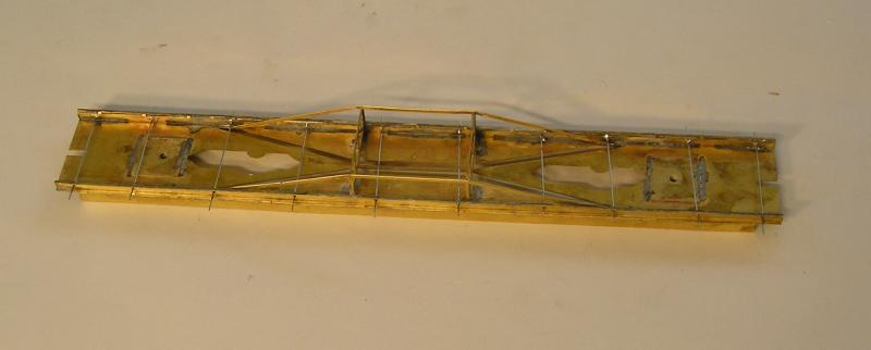
My plans went slightly ahoo because I didn't get all the wires perpendicular - no matter, as you'll see.
Now I prepared 3mm strips of brass from the underframe fret and soldered it to the top of the wires. My fine file was a perfect fit to hold the strip on the wire as I soldered.
Once both step boards were on, it was a matter of trimming the ends of the wires and cleaning up any egregious excess solder. Re fluxing, spreading with the iron and using a glass fiber pencil works well. You may need to do this a couple of times. Once I was happy that no further soldering was needed, I trimmed off the wires inside the underframe.
The step boards are on and in a reasonably close approximation of where they should be.:pathead
I can use the jig when building the other coaches.
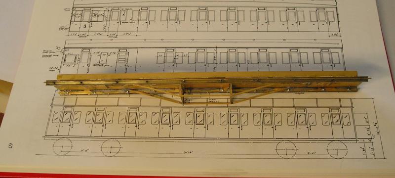
The book is Historic Railway Carriage Drawings, LMS and Constituents, by David Jenkinson.
John
Last edit: by Brossard
John
Posted
Full Member
As I mentioned, the underframe is used as a jig. The ends are screwed on and there's a slot in the floor for adjustment. It is a butt joint so needs careful lining up before tacking a couple of times. All pretty straightforward.
John
Last edit: by Brossard
John
Posted
Full Member
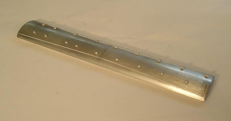
As mentioned above, this is extruded aluminum. First it had to be cut to length - that was hard work because the metal is thick and harder than brass. There was a small amount of fettling needed but I'm impressed with the precision of the fit.
Next, I marked and drilled the holes. Comet recommend that the roof template on the instruction sheet be cut out and stuck on with double sided tape, so that's what I did. I should have taken more care making sure the template was centered, but as it happened I got it right by eye.
The holes for the ventilators and grab handles were marked with my 0.020" drill, then the template was removed. Again drilling all those holes was hard work through the thick hard aluminum.
The rainstrip was carefully marked out with the position of the high spot at the center and the two end spots. I used plastic 0.020" rod. First I place the rod on the center spot and tacked it with a small dab of cyano. I then let the rod fall naturally to the ends and tacked those. The cyano goes off quickly and I then went over the length of the rod with more cyano until complete. It turned out well.
Grab handles are 0.31mm NS wire cyano'ed in place.
Torpedo vents are supplied as castings and these were also fixed with cyano.
John
Last edit: by Brossard
John
Posted
Full Member

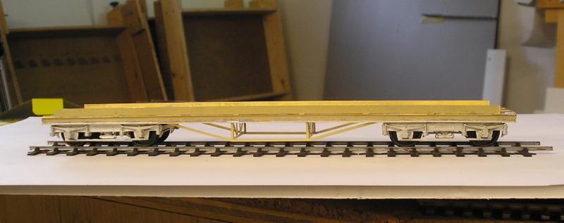
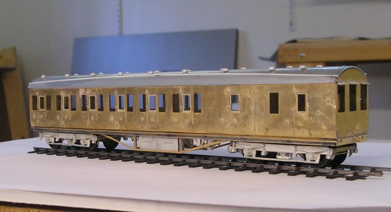
On either side of the center trusses are vacuum cylinders and V hangers for the push rods. To the right is the dynamo. I did try to add a representation of a belt but it kept fouling the bogie.
Top center is the battery box and bottom center is the voltage regulator - a great fiddle trying to solder things at different temps and an awkward angle. Finally managed it though.
Everything is soldered including whitemetal to brass - I haven't melted anything.
John
Last edit: by Brossard
John
Posted
Full Member
John
Last edit: by Brossard
John
1 guest and 0 members have just viewed this.