Johns 7mm Wagon Workbench
Posted

Full Member
John
John

Posted
Full Member
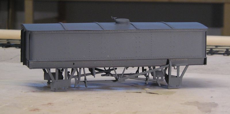
Here's where I left off last night. Solebars on along with overlays. Angled beams also added.
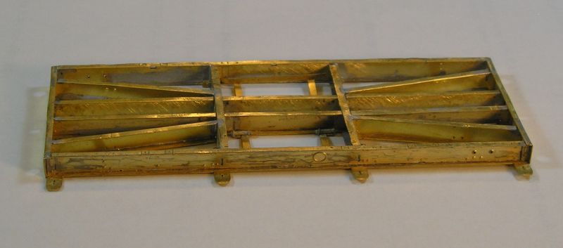
There will be a number of corner and angle brackets to put on.
John
 Last edit: by Brossard
John
Posted
Full Member
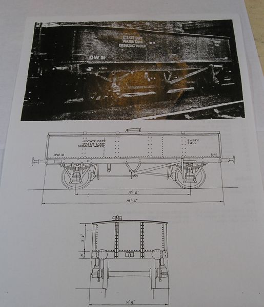
The other kit is of a GWR Drinking Water Tank Wagon, something I hadn't even heard of before now. It is etched brass from Dragon models:
http://www.taffvale.wales/index.php
The kit requires wheels and couplings and these are on order from Slaters.
There's a bag of decent looking whitemetal castings and turned buffers.
I had a debate on RMWeb about the colour of the wagon. The notes say dark green with yellow lettering, but WR BR Departmental stock in the late 50s was typically black with white lettering. There are no commercial transfers that I know of so I will have a go at making them myself.
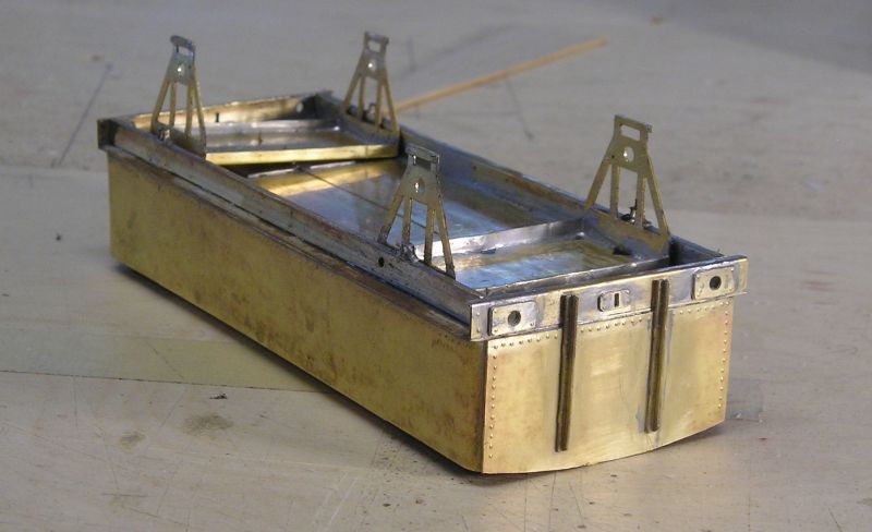
I thought I'd make a start this evening by doing the tedious job of punching out rivets:
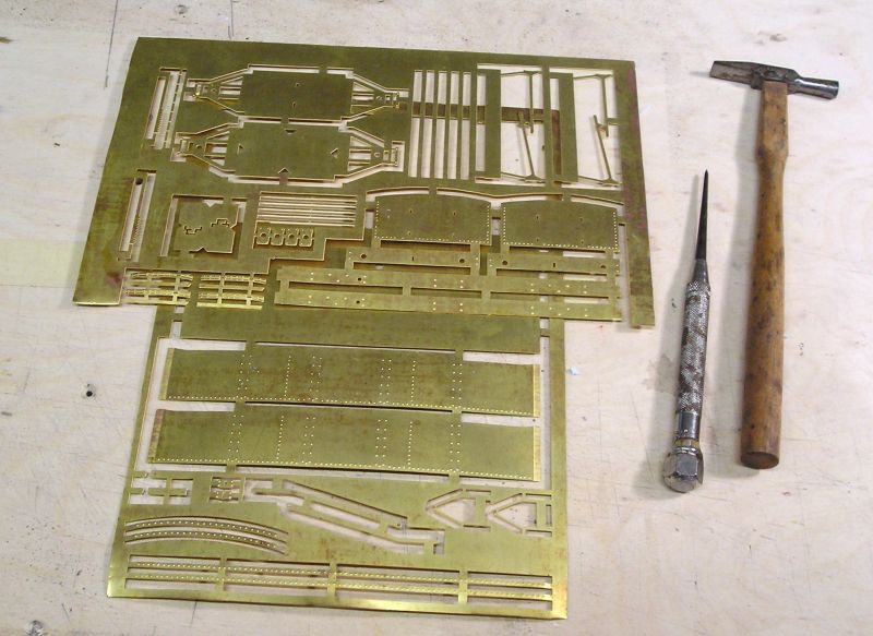
You can see all the rivets. Not too difficult really. I rest the brass on a piece of good quality plywood (you can use a cutting mat too) and use the scriber and hammer to knock them out. Three moderately firm taps with the hammer brings the rivets out.
John
Last edit: by Brossard
John
Posted
Full Member
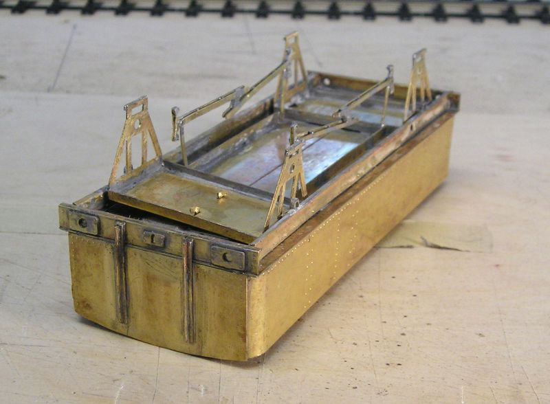
The sides are slightly long I think. There's a half etched rebate at each end of the side where the ends are supposed to sit. I had to file the end curve to blend with the half etch to get a decent fit.

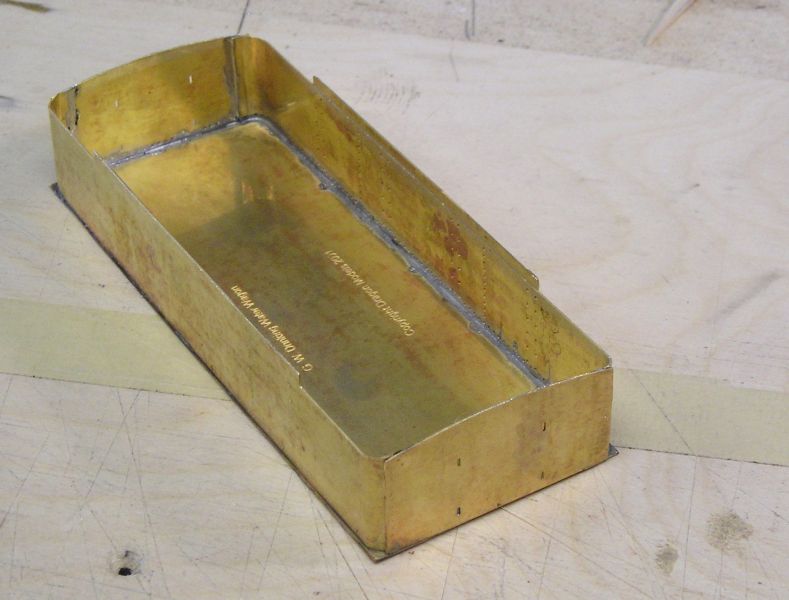
I'm using my Weller variable temperature soldering station for this, 50W rating. There is a lot of metal mass and I set the tip temp. to nearly 400C (I normally use 345C) to get the solder going. The solder is DCC concepts 145C (I suspect it is lead free, something I usually don't like, but this seems to work OK). My flux is Tix which I can get at my local hobby shop.
An interesting thing to note is that I could see the tip temp take a dive from the nearly 400C set point to around 360C whenever I applied solder. The flux, solder and workpiece will all absorb heat and the iron must have the cajones to recover quickly.
Solder was applied in a series of tacks working at one end of the piece, then the other. The tacks were eventually joined together in a seam. It's always a good idea to start with a couple or three tacks. You can then inspect alignment and squareness. It is easy to undo a tack to make a correction. Trying to undo a seam is very difficult.
John
John
Posted

Full Member
How do you plan to tackle the over long ends? iI might have been tempted to shorten the ends before fitting them.
Regards Rob
Posted
Full Member
John
John
Posted
Full Member

Looking more like a wagon now.
The rocking W iron unit provides compensation.
I am stuck now waiting for wheels which were ordered getting on for 2 weeks ago.
I spent a lot of time scraping off excess solder and generally cleaning up.
John
John
Posted
Full Member
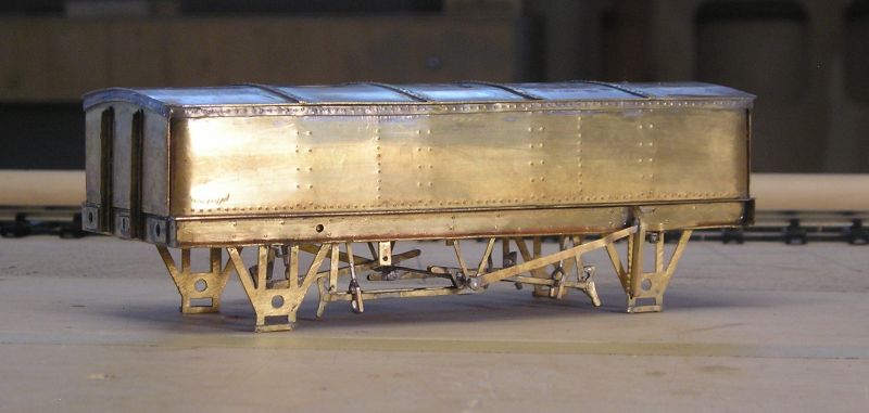
So, out came the Dremel and I set out to basically scratch build the brakes using the kit etch as a basis. I carved shoes from some scrap strip, 8 in all because they needed to be double thickness.
It took a while but here is the result:

Plastic kit and RTR manufacturers would have us believe that the brake push rods are solid. They're not and comprise two parallel bars linked to the brakes. I did need to fettle the clearance between brake and wheel and the wagon is running freely. The wheels weren't fixed and quite sloppy so I expect I'll have to do a bit more when the proper wheels arrive.
John
Last edit: by Brossard
John
Posted
Full Member
Just wait until you get to the brakes on the MMP Kit John, all your brake gear fantasies will come true.
Regards Rob
Posted
Full Member
Annoyingly, I found whitemetal brake shoes in the castings bag so I've reshaped my shoes to suit.
Must get back to the MMP soon.
John
John
Posted
Full Member
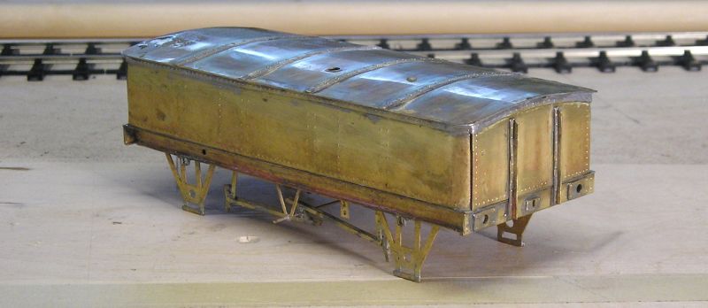
Rivet strips on the tops of the ends and sides. Roof on (what a PITA!) and more rivet strips. Almost there really.
The rod between the V hangers is temporary and will be cut off. Brakes were independent, ie you could only apply brakes on one side at a time.
John
John
Posted
Full Member
Spigot brackets, brake lever ratchet and lever as well as safety loops.
It is currently taking a bath in white vinegar.
John
John
Posted
Full Member
Presumably the white vinegar cleans away the crud that accumulates during the build? - A new one on me.
It is currently taking a bath in white vinegar.
John
Regards Rob
Posted
Full Member
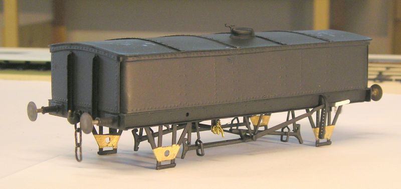
Working on the W/M bits now, although I haven't got wheels yet so can't fit springs, axleboxes and brake shoes.
Probably prime later today.
John
Last edit: by Brossard
John
Posted
Full Member
I masked the bearing holes since I need to solder those in when the wheels finally get here. I'll paint the black tomorrow after the primer has had a chance to cure.
John
John
Posted
Full Member
I used Slaters instanter couplings and vacuum pipe.
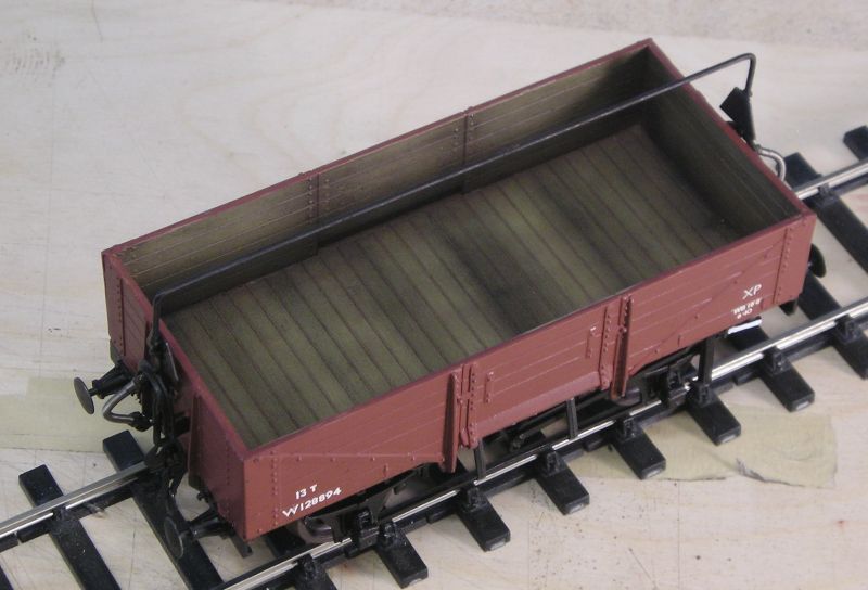
I tried to make the interior look like natural wood that has seen service.
John
John
Posted
Full Member
Regards Rob
Posted
Full Member
John
John
Posted
Legacy Member
I mentioned above that I had a commission to build two kits. Besides the water tank, the other is a GWR Dia 033 from Parkside:
Hi John.
I used Slaters instanter couplings and vacuum pipe.
I tried to make the interior look like natural wood that has seen service.
John
Those Slaters instant couplings. How do they work and can they be fitted to an O Gauge Dapol Terrier and there wagons ?
Thanks.
Allan
Posted
Full Member

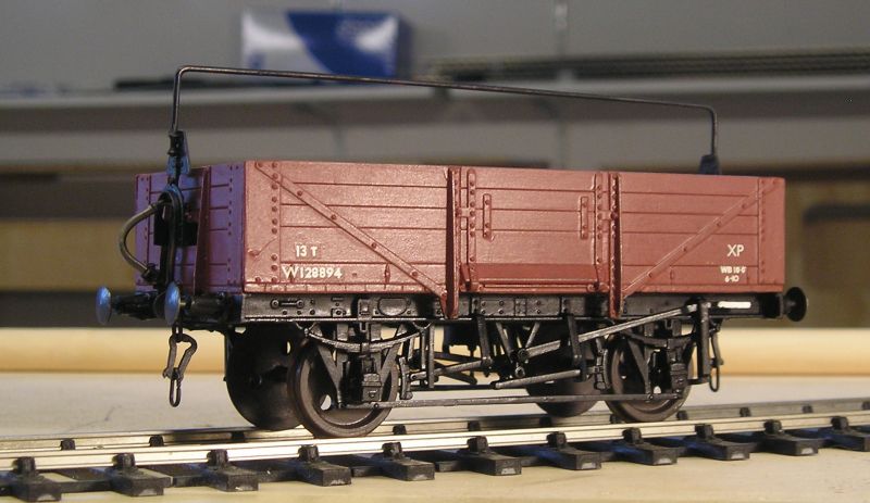
I think I've gone as far as I can:
I'm very pleased with how this turned out. I used Testors rattle can flat black. I gives a nice finish but already, because of handling I can see scuff marks.
Couplings: These are Parkside, robbed from the GWR kit. I finally twigged that the top link needs to be soldered closed so it doesn't fall out of the gap in the coupler.
Buffers: The kit contains 6 castings which are essentially whitmetal tubes. These require careful drilling to ensure that there are two different internal diameters for proper buffer springing. I did scrap one of them when my drill went to far. I also noticed that the springs provided were not all the same and quite large too. I replaced them with finer springs (Slaters I think). I was also annoyed that the holes in the buffer beam are smaller than the nut so I had to do the nuts after installing the housings in the buffer beam. Fiddly but doable. I finished off by securing the nuts with thread locker LocTite. I don't recommend using CA because you can break the threaded part off if you ever want to remove the buffer.
I painted the spigots brass and touched up the brake handle with white.
I also worked on the transfers. A dreadful disappointment but I got some usable decals.
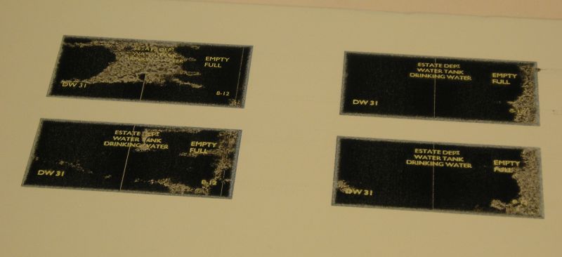
I used Microscale white backed sheets and the instructions do say that these are really for laser printers (although my old Samsung laser made a mess too). I sprayed some dullcote on the sheet before printing. The good news is that my all singing and all dancing printer does feed the sheet. I finished with some Testors decal coat.
You will see that I can get one set of the lettering, but most of the Tare numbers are rubbish. I can use numbers from my (now) extensive collection of transfers.
John
Last edit: by Brossard
John
1 guest and 0 members have just viewed this.