Johns 7mm Coach Workbench
Posted

Full Member
Regards Rob

Posted

Full Member
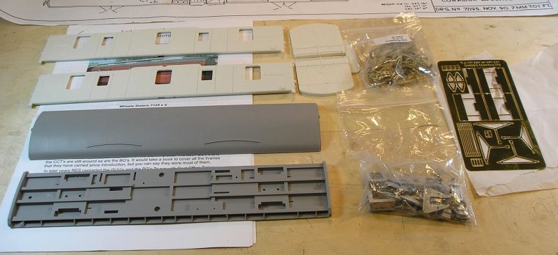
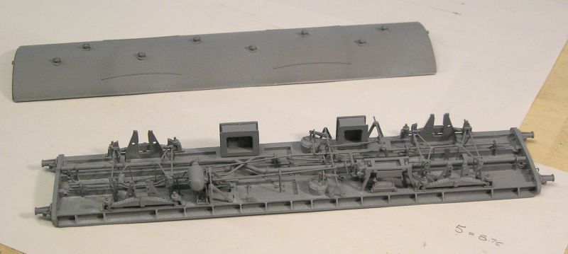
Resin body parts, lots of whitemetal castings, lost wax brass castings and an etched brass sheet.
Most of the assembly will require the use of CA glue.
Here's where I stopped this evening:
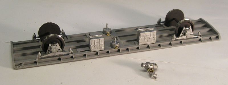
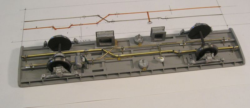
W irons and springs installed along with battery boxes and vacuum cylinders. I've been detailing the dynamo.
The axle boxes are free to slide in the W irons. I've rigged up a post on the nearer axle for some compensation. The wheels aren't fixed yet, I'll hold off on that until I'm sure (well as sure as one can get) that any underframe detail won't get in the way.
The instructions are a bit sparse although there are colour photos. Some while ago I bought a second hand 4mm Masterclass CCT kit. Very OCD but I can use that to help me with some of the finer points. The kit designer makes some Flickr galleries available that contain kit pictures as well as those of the prototype.
John
John
Posted
Full Member
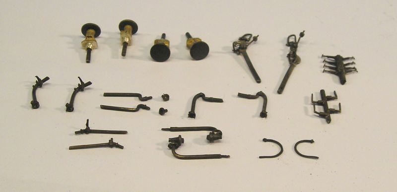
Most of these go on the buffer beam. I spent ages opening up the buffer housings to get a smooth sliding fit for the buffers. The screw couplings were hard work as well and took some figuring out. Again a lot of fettling to get things to fit. These are cosmetic in that they don't screw up as the Slaters do.
Next row are steam pipes and vacuum pipes (I'll use a Slaters spring hose). Are the next ones another version of vacuum pipe? There are also T handles and door handles.
I don't recognise the castings on the bottom row. My suspicion is that they have to do with later configurations of the vehicle. If anyone has an idea I'm interesting in knowing.
I mentioned that I installed a rocking axle for compensation:
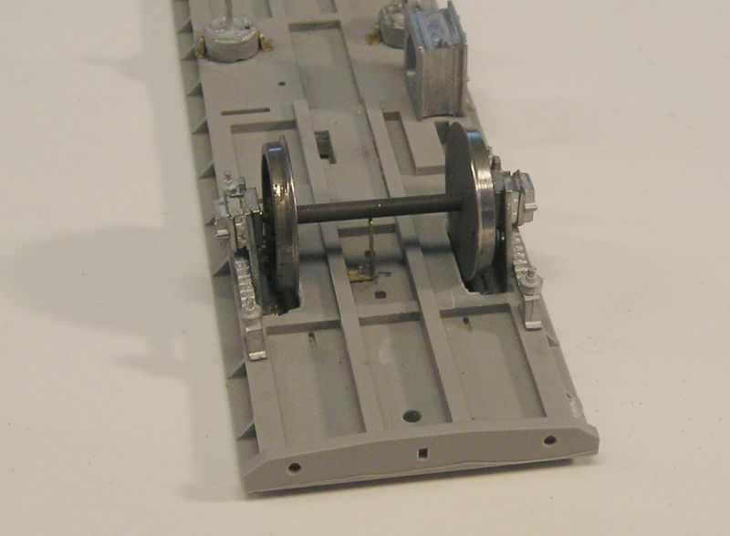
Dead simple really. The only trick is getting the pillar height just so. Mine is arranged so that there's about 0.5mm of play.
The other axle has a sheave for the dynamo belt:

It's not fixed yet. I need to install the dynamo first.
John
 Last edit: by Brossard
John
Posted

Inactive Member
Max
Port Elderley
Port Elderley
Posted
Legacy Member
Allan
Posted
Full Member
John
Posted
Legacy Member
Posted

Full Member
Bill
At 6'4'', Bill is a tall chap, then again, when horizontal he is rather long and people often used to trip over him! . . . and so a nickname was born :)
Posted

Full Member
That dynamo sheave is a nice touch. Pity it's not done in 3.5 or 4mm scale as they're big and obvious. Are there plans afoot for a working belt?
Nigel
©Nigel C. Phillips
Posted
Full Member
I think I can run a piece of brass strip to be in loose contact with the sheave.
John
John
Posted
Full Member
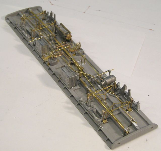
I made a 1:1 sketch for my model and spent the day constructing these:
Both vac and steam pipes were 2" nom. diameter pipe. However, the steam pipe was lagged makng it 3" dia.
The device teed off the vacuum pipe is a Direct Admission valve. It detects a drop in vacuum and makes brake application more even in the rake by dumping the vacuum to atmosphere. I get cleverer every day. :hmm
You can also see my dynamo has had a power cable attached to the junction box along with grab handles. Theres a safety chain as well but that's hard to see.
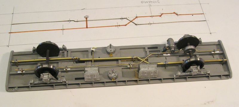
View from the other side.
Now I only hope that the addition of all this hasn't mucked up the installation of other parts.
BTW, these pipes are quite visible if you're at ground level. They are about 3" below the level of the frames.
John
Last edit: by Brossard
John
Posted
Full Member
Regards Rob
Posted
Full Member
John
John
Posted
Full Member
Looking very busy and we're nowhere near done.
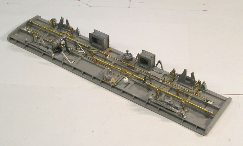
Brake yokes, safety loops and brakes installed. This took a fair while because I needed to stop and let the glue dry thoroughly after each step.
Main V hangers on. I drilled these at the base and soldered in some wire. I then had to carefully line everything up using a template to drill holes in the chassis. Happily everything worked. I have a distrust of relying solely on CA for small items like these. I like to pin where I can.
I made brake actuator levers but these aren't on yet.
Cast hangers are installed at each end. My piping did mess up one of these so I cut it up and glued the separate pieces in.
My plan is to hold off on the final securing of the wheels until after I've painted the underframe.
I will need to make brake rod levers myself since the kit doesn't include these. As far as underframe detail is concerned, the kit is pretty basic.
John
John
Posted
Full Member
I cannot imagine how anyone coming into this kit cold and relying solely on the instructions could do it. I got a ton of help from the guys on RMWeb: BR Mk 1 CCT in 7mm - 7mm+ modelling - RMweb Lots of detail photos of the underframe. There's a drawing showing how the cylinders are plumbed and how the Direct Admission Valve fits into the picture. No info in the kit on this either.
I had to give my leetle grey cells quite workout to figure out how the brakes work. Fairly simple once you know.
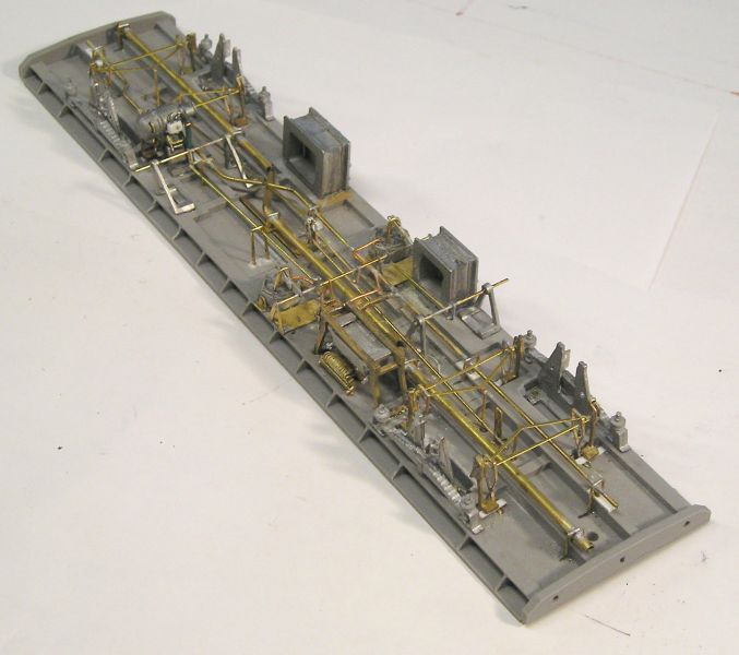
The key is a reversing lever mounted on the centerline and just in front of the vacuum cylinders in the upper picture. This was not supplied nor was the rigging even mentioned. Happily I was able to use my Masterclass 4mm kit as a reference.
For those interested here's how it works:
The main actuating rod is mounted on two sets of V hangers. Beside the levers coming of the cylinders, there are three mounted on the rod. The middle one is critical. It pulls the reversing lever at the mid point, exerting a pull on each rod that actuates the main brake yokes (here I just soldered the rods to the yokes).
There are two other levers linked to the handbrake actuators. These can be seen with rods sticking out waiting for me to attach the brake lever.
I need to fab. a dynamo belt and fix it.
Other than that, we're about done.
John
John
Posted
Inactive Member
The voyeur in me is loving watching you work. :cool:
Max
Port Elderley
Port Elderley
Posted
Full Member
Posted
Legacy Member
Brilliance just isn't the word for it.
Allan.
Posted
Full Member
John
Posted
Full Member
All primed up and ready for final painting.
Working on the body. This has been assembled and is in paint.
John
John
1 guest and 0 members have just viewed this.