Track and soldering
Posted
#123857
(In Topic #6482)
Inactive Member
Soldering dropper wires to rail can be a pain, just maybe another way.
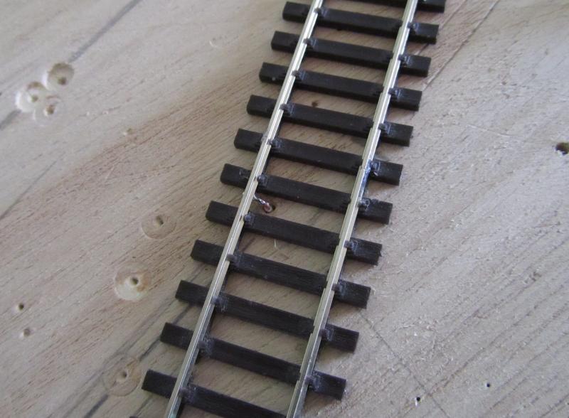
:hiAll, I was mulling over this soldering wires to rails and with DCC and droppers there is a load of soldering and if the track is already down it can be right awkward to get at.Anyway, This may have already been thought of.
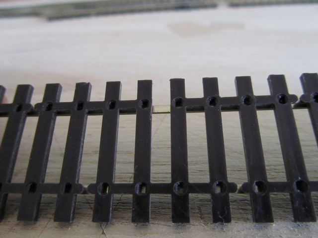
Take your length of Peco or whatever track, At one or both ends solder a copperclad sleeper leaving a rail overhang for joiners.
Gap your sleeper to stop shorts.
Now when your track is laid, You have a nice handy sleeper to solder droppers too, A darn site easier than trying to solder to a code 75 rail or smaller even worse when its the far rail

When happy paint your sleeper.
regards,
Derek

Posted

Full Member
Using a small length of rail, with one end suitably wrapped in a cloth to prevent the heated rail buring the fingers, loosly push a rail joiner on to the end. Tin, then solder the wire to the underside of the joiner.
Stu
Stubby47's Bespoke Model Buildings
All photos I post are ©Stu Hilton, but are free for use by anyone.
Posted

Full Member
Mal
All stressed out, got addled brains?
Ride your bike or play with trains!
Ride your bike or play with trains!
Posted

Legacy Member
Posted
Inactive Member
Good one Stu.
Another tidy method from you Mal,
Regarding the bracing cross-timbers, As I have no scenic,s I just scribe 2 pencil lines across the base-board, the width and directon of the cross-timber, Then I know exactly at a glance were the beggars are, handy for were not to have a point motor position, hehe.
Well Gordon, All credit to you with the copper sleeper,s
Its a very handy method.
thanks for the posts guys.
Derek
Posted

Inactive Member
Max
Port Elderley
Port Elderley
Posted

Inactive Member
I'm with Max on this. The rail joiners often get full of muck over time and don't give good conection.I'm not conviced about soldering the wire to the joiner, Stu. Droppers need to be soldered to the rail, or to the copper tie, which is soldered to the rail. The joiner still has a dry joint to the rail.
Soldering rail joiners to rail is not a good idea either. Does not allow for any rail expansion.
Ask me how I know.
Any DCC is better than no DCC
Posted
Guest user
I'm with Max on this. The rail joiners often get full of muck over time and don't give good conection.
Soldering rail joiners to rail is not a good idea either. Does not allow for any rail expansion.
Ask me how I know.
I do solder the odd fishplate to rails especially in the middle of curves - this is done when rails are straight, helps with a nice curve at the join & no dogleg.
So far with temperature varying from 6 - 35C in the room, no problems & I even had soldered rail of 9 ft in length to PCB sleepers with no movement or breakages as the PCB sleepers were pinned to the track base every 4" and some had also been ballasted.
Posted
Inactive Member
Posted

Full Member
I'm not conviced about soldering the wire to the joiner, Stu. Droppers need to be soldered to the rail, or to the copper tie, which is soldered to the rail. The joiner still has a dry joint to the rail.
………then, maybe take a leaf out of the 'G' scale outdoor electric powered chappies book, and put a minute smear of graphite grease on the fish-plate? They exist outdoors in all weathers, earwig-poo, etc.
Doug
 Last edit: by Chubber
'You may share the labours of the great, but you will not share the spoil…' Aesop's Fables
"Beer is proof that God loves us and wants us to be happy" - Benjamin Franklin
In the land of the slap-dash and implausible, mediocrity is king
"Beer is proof that God loves us and wants us to be happy" - Benjamin Franklin
In the land of the slap-dash and implausible, mediocrity is king
Posted
Inactive Member

Max
Port Elderley
Port Elderley
Posted
Inactive Member
Every time I raise this, I regret doing it. Maybe this time I have learned my lesson.
Not at all Max, Variety is the spice of life

I myself would not join the bulk of the track together with soldered rail joiners,.
The great outdoors tracks usually have bridge wires soldered across the outside of the rail joins, With a nice drop of grease on the railjoiners to stop them falling to bits.
Posted

Full Member
Whenever I've read about continuity problems on model railways, it's always been either a "dry joint", a broken wire within the insulation or, and by far the most common, a lack of good contact via a rail joiner.
Unless they've changed the material, they do rust/tarnish/become dull with age - just the moisture in the air is enough over time so, in spite of those who haven't had any problems at all, I'd tend to solder to the rail itself rather than the joiner - unless I soldered to both !!!
In my former railway modelling experience way back in black and white days, I soldered to the bottom of the rail before laying the track. This was great as long as you didn't need to move the track later. As has been said, it's both easy and neat but for me, I invariably needed to move the track later - I tend to "plan as I lay" having little more than a rough idea of what it will all look like in the end.
I now normally solder to the rail web and, as my soldering improves, so does the appearance of the joint and progressively less sleepers end up looing like yesterday's British Rail sandwiches. Once ballasted and weathered, you can hardly notice the burns ………….:roll::roll::roll:
Again, it's a clear case of "each to his own".
'Petermac
Posted
Full Member
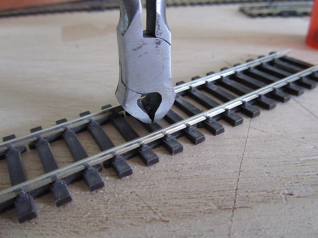
Forgive me if you have seen this before, but this is how I do it, and when it ain't cardboard I'm a bit cack-handed myself…..
First, if you are not re-spacing the sleepers, cut out the web at each space you want a dropper……
and tin the space moderately generously. Use resin cored solder, do not apply liquid or paste flux or the solder will run around the rail and fill up the web, then you may as well have soldered it there in the first place….

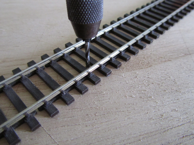
Lay the track in position, pressing Peco pins through the centre of the sleepers with a pair of pliers until there is a little left sticking up….

Cut off the sticky-up bit, flush, if you are confident of your soldering, or leave until you are finished with the soddering iron…
[Explanation * below]
Drill a hole through the baseboard about 4-5 times the diameter of your dropper, about 3/16" away from the inside of the rail…
Prepare and generously tin a dropper….

place the dropper in the hole, and wriggle it into position under the rail, then, rest the freshly tinned iron on the dropper wire ONLY and push it gently forward until the tip just touches the rail bottom. Believe it or not, this is easier to do with a screw-driver pointed 60cwatt workshop iron as you can get more heat on quickly and get out quickly, too, before anything starts to melt…..
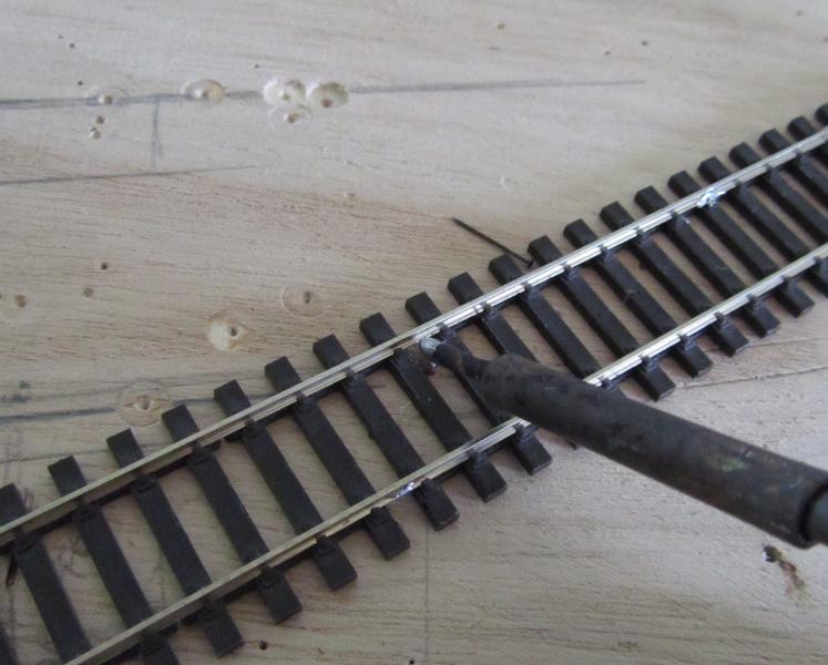
The two tinned areas should melt together to give you this……………..
I hope that has helped/explained or encouraged?
Doug
* This method of track-laying allows you to lift track without having to 'dig-out' track pin heads, and if you are a bit concerned about soldering, allows you to lift the track 1/8" to solder the dropper from below, when soldered, simply push the track back down and snip off the excess.
Last edit: by Chubber
'You may share the labours of the great, but you will not share the spoil…' Aesop's Fables
"Beer is proof that God loves us and wants us to be happy" - Benjamin Franklin
In the land of the slap-dash and implausible, mediocrity is king
"Beer is proof that God loves us and wants us to be happy" - Benjamin Franklin
In the land of the slap-dash and implausible, mediocrity is king
Posted
Inactive Member
I really must get some decent glasses so I can see what I am trying to solder
:cheers Derek
Posted
Full Member
It really must work otherwise you wouldn't have shown it but I'm surprised you can get enough heat into the rail before you melt the dropper - either the insulation or the tinning…………:shock:
'Petermac
Posted
Full Member
It needs the cavalier approach, sure, an 18 watt Antex will just do it, the 25 watt is better, but for real 'in and out' this 60 watt does the job in a split second before any plastic starts to smoke! You just need that little bit of freshly picked-up, flux rich solder on the iron to transfer the heat to the metal before the radiant heat does any damage.I'm surprised you can get enough heat into the rail before you melt the dropper - either the insulation or the tinning…………:shock:
http://bit.ly/j6CsLY
I've just put my camera battery on charge, or I'd photograph mine, looking a bit battered now….
Doug
'You may share the labours of the great, but you will not share the spoil…' Aesop's Fables
"Beer is proof that God loves us and wants us to be happy" - Benjamin Franklin
In the land of the slap-dash and implausible, mediocrity is king
"Beer is proof that God loves us and wants us to be happy" - Benjamin Franklin
In the land of the slap-dash and implausible, mediocrity is king
Posted
Inactive Member
If you have a situation where you need to solder the track together because of design challenges (tight bends etc.), special needs may dictate special responses. However, if you solder the track together and bend it, when you come to Dremel a new break in the rails, often the residual tension will allow the rails to pop out of the chairs. (How do I know this?)
It's not important how you effect the joining of the droppers to the rails, except that every piece of rail needs a soldered dropper (including each part of your turnout assemblies), and soldering to the inside of the rail is asking for trouble. Once every piece of rail has its own feed, the copper buses and sub buses can be arranged in any way you want.
Soldering to some people is like scenery is to me. I'm not very good at it, but I keep trying to master it. Rather than tyring to find work arounds to avoid it, a much better idea is to keep practicing.
Rant over.
Max
Port Elderley
Port Elderley
Posted
Inactive Member
My layout is in an unlined tin shed in an Australian state where the temeratures in summer can get over 40C and so far my track has not moved for over 10 yrs.
My power feeds to every piece of track on layout is a small copper wire soldered to the side of rail after the track is layed then connected to power dropper under layout.
Once the rail is rust coulored and ballasted properly the small soldered wire on the rail side is hardly noticable.
If you look at real rail there is often fairly thick wire attached to side of rail for signalling,railcrossing operation etc.
As has been said, to each their own, what works for them etc.
Ian
Any DCC is better than no DCC
Posted
Full Member
I can see that, electrically, there would be no need to use them given that there's a dropper to every bit of rail but I use them because they're stronger than plastic ones. Also because, contrary to every bit of advice I've ever been given, my idea is to have a dual system - DC or DCC (but naturally never both !!). Maybe I should lay my track better and take out the stresses first rather than relying on the joiner to carry them ………………….:roll:
'Petermac
1 guest and 0 members have just viewed this.