Hand laid track using copperclad
Posted
#172448
(In Topic #9760)

Full Member
How to get that bit of daylight underneath
Hand built track and copper clad.I'm in the process of building track for my layout. This is EM gauge, GWR 2-bolt chairs. Having made enough inside chaired track using C+L products (7 feet or so using thin sleepers, code 75 B/H rail), it's now time to get on with the track and turnouts for the main part of the layout. I'm planning on using plastic sleeps with a copper clad every 10 sleepers or so, plus extensive use of the copper clad in turnouts. One thing I don't like about copper clad is that a thickness equal to the sleeper plus the base of the chair is normally used, and this makes using cosmetic chairs difficult as they sit too high, and the perception of daylight under the rails is lost when ballasted.
I came up with the following jig to help me get the right height of the rail above the sleeper, thus allowing me to get the solder between the rail and the copper clad at a reproducible thickness, and subsequently allow me to glue the chairs (after cutting in half and trimming) so that they do not sit proud. Please feel free to use or modify the procedure described for your own use. I retain copyright to the procedure, acknowledgement of such appreciated.
This procedure is for the copper clad and sleepers described below, adjust to your specific requirements.
Materials:
Copper clad, 2 sided, nominal thickness 1.06mm. Scale 12" wide. C+L Finescale (corresponding to turnout timber).
100°C solder (Carrs).
145°C solder (Carrs).
No clean flux, DCC Concepts.
Brass sheet, K&S metals, 0.6mm.
Procedure.
I cleaned the brass and copper clad (#600 emery + 90% IPA), coated half of one side with solder, and then sweated the copper clad to the brass sheet such that it would cover a span of 10 sleepers. In use, copper clad sleepers are positioned over the template using double-sided tape, and the jig slid between the sleepers. Rail is soldered to the copper clad as usual using appropriate gauge spacing tools. I use 145°C solder, and just enough to go in the gap between the track and the copper clad. The jig copper clad is kept several sleepers away from the soldering, and I use large metal pegs clipped to the rail as heat sinks.
Plastic chairs are cut in half (use a magnifying light), trimmed, and glued in place. I did this before painting, in hindsight do it afterwards leaving a small area unpainted for the chair halves. I used 5-15 second CAA applied with the end of a paperclip.
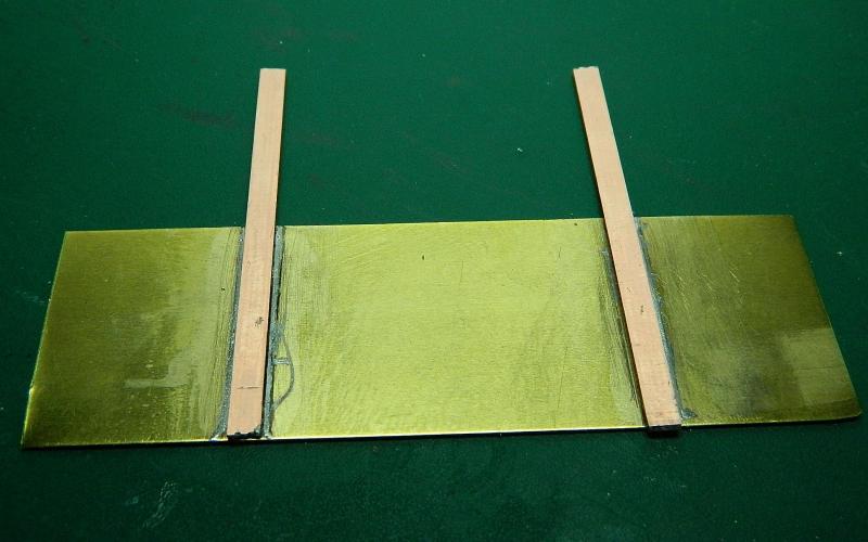
The jig.
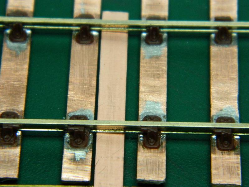
Jig in place with some finished track.
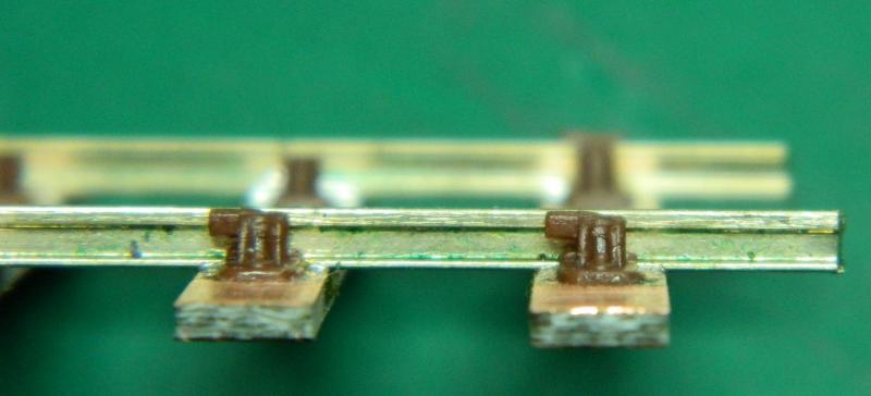
No jig - the chairs sit too high.

With jig. This was with a 0.5mm rise, 0.6mm is better. Adjust to requirements.
Nigel
©Nigel C. Phillips

Posted
Full Member
Terry
 Last edit: by col.stephens
Posted
Full Member
I agree, C+L components are inherently weak, especially the chair to sleeper bond which is supposed to use MEK. Slightest lateral force and the chair detaches. This may be available in the UK (as Butanone), but difficult to get here in less than a 40 gallon barrel. I have to use a Testors brand which contains MEK (and other things). There is a MEK substitute in the US which I have yet to test. The bonding to wood is actually better than to the plastic sleeper. One copper clad every now and again is just about as tedious as putting the two chairs on the rail (and a lot faster, I timed it). I will need them at the end of the modules as well (just to make sure). It also provide a bit more security on curves where the curve in the rail may not exactly match the required track curve. I was test fitting some track to the track plan 10 minutes ago, 2 chairs popped and will have to be re-glued.
Turnouts are something else, I have 12 to do and plan on using a lot of copper clad. The jig was really intended for those, rather than the regular track. Nothing more incongruous to my eyes than track with prototypical chairs juxtaposed to a copper clad turnout with the track flat against the sleeper.
I was using 12" wide sleepers (turnout size) for the jig and example, I'll use 10" for the regular track.
Nigel
©Nigel C. Phillips
Posted
Full Member
Anyway, my point (no pun intended) about C&L turnouts being weak was not in relation to the chairs coming adrift, more to do with the fact that as C&L do not produce the full range of chairs which are used on the prototype turnout, you are forced to compromise by sticking half chairs in various places, resulting in the rail not actually being held in place by certain chairs. Accordingly, the point is often damaged by the double-sided tape holding it to the turnout plan, when removing it.
Re the plain track, why don't you just use C&L ready made track and save yourself all the hassle of making it yourself? It looks good and is as strong as any of the other ready made track.
Terry
Last edit: by col.stephens
Posted
Full Member
Hope you're standing at attention. MEK (methyl ethyl ketone) is known commercially as Butanone. Yes, it melts the chairs, unfortunately the plastic used for the sleepers appears to be a lot more resistant as far as I can see. Helps if it's roughed up a bit. Evergreen styrene is even more resistant (but a lot cheaper). I shall try the MEK subsitute to see if it's any good (ethyl acetate based). Supposed to be safer, but that's all relative. Still needs a good air evacuation system.
Why am I giving myself this grief instead of RTR track? Inside chairs and blocks on one of the sidings, a mix of 8' 6" and 9' sleepers (even in the late 1950's), and I need GWR 2 bolt chairs (the RTR is 3 bolt). Plus the chair blocks all point one way on the RTR, on branch lines they were alternated. All of which are noticeable. I know the chairs are handed (the angle of the rail), it actually makes no difference if the odd one points the other way. Plus which the RTR track is 36" long and therefore incurs horrendous shipping charges for overseas.
Nigel
©Nigel C. Phillips
Posted
Full Member
You won't have that trouble with C&L track Nigel, they haven't got any!
Terry
Posted
Full Member
Quite right, decent looking chairs though. The chair blocks are actually a bit under scale, but at least they're there. Another reason to DIY. The Exactoscale GWR 2-bolt brass castings are superb, but at £6.00 for 8, and 38 required per 45' track section, that's £28.50, and probably upwards of 200 sections……….Useful to have a few on turnouts though.
Although even with the plastic ones I was sorely tempted to bury the lot under ballast circa 1880 and spend the money on period engines.
Forgot to mention, copper clad has another useful function when positioned every now and then - soldering circuit wire o the rails, which in my case can be positioned between the rail and the sleeper with the hole in the sleeper.
MEK. I should know better - butan-2-one, usually termed 2-butanone.
Nigel
©Nigel C. Phillips
Posted

Full Member
Sorry to sound thick but I don't see the daylight under the rail.
I've seen experiments where chairs fixed with butanone fail at the rail fixing first rather than the timber/chair interface.
I don't think I'd rely totally on the chairs by themselves but bodge either with strategic copperclad or partial riveted construction and half chairs. Two areas bother me: the crossing needs to be especially strong and the timbers fitted with slide chairs tend to fall off.
John
Last edit: by Brossard
John
Posted
Full Member
That's because it's filled with solder. A space between rail and ballast is the aim here. Soldering directly to the copper clad and ballasting level with the top pf the sleeper = no gap. Trying to get a blob of solder exactly the same width as the chair is beyond my limited soldering skills (and patience). I've yet to find a needle file narrow enough to file excess solder away.
Nigel
©Nigel C. Phillips
1 guest and 0 members have just viewed this.