Static Grass Applicator - DIY Built
Posted
#237195
(In Topic #13119)

Full Member
Another take of building a Static Grass Applicator
I know there's been a few write-ups on this subject before but nothing for a while and things tend to move on. So here's my take on it.After numerous searches and videos watched, I decided on a DIY version as opposed to putting my short arm into my deep pocket and buying a ready built unit. A compromise of designs came to light. I liked Luke Towan's "Static Grass Applicator – Professional Tools for Modelers" https://www.youtube.com/watch?v=ZO1jrUL_PLU and his earlier version. But the cost of the negative ion generator he used from Oatley in Australia made the price more than I could realistically justify - AU $14 for the generator (minimum order value AU $20 on credit cards) plus another AU $20 or so for postage (a total of around £19.50) - and then there's the cost of the other bits required on top. Ebay also sells the Oatley unit with a price tag of US $22 (around £17.50) plus postage which, it states, they may not deliver to the UK! The unit from Oatley, according to their website, gives around 12Kv as opposed to the bug-zapper variety that gives only 1Kv or so or other ion generator units from the far east giving around 6Kv.
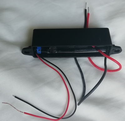
Searching further on ebay I came up with a "12v in for 15-20Kv out" unit (now that's more like it!) for around £6 (guess where from!) and this was to be incorporated into something akin to that in Luke's video. The size on the web pages gives a strangely written size of 60*70*30mm - no matter which 'site' is viewed - whereas in reality it comes in at something like 125x22x32mm, although one page did give the more accurate figures. One look at the picture clearly shows the dimensions were incorrect. But there you go. This unit I'm building, like Luke's, runs from an external 12v supply or an internal 9v battery.
One thing I need to strongly emphasize for those unused to dealing with high voltages like this is that these devices have the possibility of killing anyone that comes into contact with the metal grid at the end of the device. There's not a lot of current being delivered to the metal grid but the voltage will certainly give a very nasty jolt and anyone with a dicky heart (known or otherwise un-diagnosed) could be at risk. Certainly keep away from children whether it be switched on or not (they know how to fiddle with switches!).
After much time (many hours) trying to decide which would be the better option to use - 40mm or 50mm pipe - I decided that the 40mm option would be a better bet; at least in my own mind it was a better option. The 50mm pipe allowed an lot of spare space around the ion generator and meant that it needed to be secured to the pipe-wall and that meant screws on the outside of the pipe. Whereas, with the 40mm option - first off, no, it wouldn't fit inside. And yet I still chose it.
What - are you crazy?
Yes, probably!
I decided that if I were to cut a slot in the pipe-wall the width of the ion generator, only a small part (a couple of mm only) would be protruding over and above the pipe-wall and the ion generator could be glued at its base inside the pipe and also around the cut edges of the pipe where it protrudes (i.e. no outward bolts on the pipe). This meant that the pipework needed to be black to match the colour of the ion generator. The pipe would not, I doubt, suffer much if any loss of strength by the cutting of a 22mm slot over 100mm of its length.
For those of a technical nature, the inside diameter of the 40mm pipe is 38.1-39.3mm and 51mm for the 50mm pipe (according to Floplast Tech.). And the outside difference between the two pipe sizes is only about 3/8" which, again I felt, made quite a difference in its probable handle-ability.
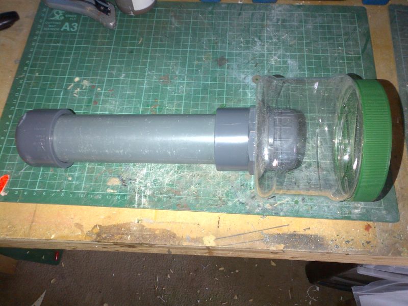
The main body of the device will be put together using Floplast Solvent Weld 40mm pipe, a Straight Coupler and a Blanking Cap from McAlpine (only available in white! Bother!). The Cap will allow the mounting of the switch, the external power socket and an LED and still allow me access to replace the battery when needed without unscrewing a cap with these bits on and inevitably getting the wires twisted and running the risk of twisting any of the wires off due to stressing them by unscrewing.
The container used is the same as Luke used - the Sistema BreakfastToGo 530ml Container. Other suitable containers are available at less cost but the clips seem to be more of the flexible plastic type whereas the Sistema used more of a proper hinge style and will, I feel, last much longer. Probably well worth the additional cost on this one item.
The only other parts used are a DPDT switch, an LED, a plug & socket for the external power, a tea strainer for the mesh and some rapid setting epoxy glue. Also, a 9v battery and its connector if you wish to make it a fully portable item.
I decided on the portable (9v) device but I only used one LED to indicate power was being applied. As to which power source was being used didn't bother me - the switch position said it all - internal 9v or 12v external.
Anyway, that's the background. I'm just awaiting the ion generator to arrive in the post (any day now!) and then I'll get the rest of the bits together and get it built and tested.
More as and when…..

Posted
Full Member
I bought one someone had made, doubt I could have made it cheaper, plus I’d have probably killed myself in the process!
Posted

Full Member
Ian Lancaster
Please visit my OO Gauge 1930's LMS layout "Jencaster"
http://yourmodelrailway.net/view_topic.php?id=14622&forum_id=21&page=1
Please visit my OO Gauge 1930's LMS layout "Jencaster"
http://yourmodelrailway.net/view_topic.php?id=14622&forum_id=21&page=1
Posted

Full Member
This is the sort of thing that makes this forum great.
I made a fly zapper version that I’m very happy with.
Will be interested to see how much more grass you can stand to attention at once with your souped up version.
Cheers
Marty
Posted
Full Member
I think I can get away with making the whole project on around £20 tops. Which I think, for an device of this power, is pretty good. We'll have to see how long the grass strands to be used I can get away with getting them to stand on end. We'll see.
This is a essentially a DIY report "on-the-build-as-you-go" exercise; meaning I'm posting here as I'm working through building it. So what you'll get is warts and all!
Building or not, as the case may be. I'm still waiting for the ion generator to arrive in the post - it was supposed to be here by today - and it's not yet arrived; so I'm none to pleased at this time. But patience is a virtue I'm told.
I have, however, been giving it all further thoughts, mostly about the main body of the project - the pipe - and what size I can build it into. First off I was going for 50mm and then 40mm then back to 50mm, etc. I had ideally wanted to build it into 40mm solvent weld pipe (easier to hold) - but I didn't have any; only a short length of 40mm compression pipe. Are they compatible? No, of course not. That would be too much to ask. There's not much difference - about 2mm in outside diameter - the solvent weld being the slightly larger. The solvent weld pipe gave a closer fit for the solvent weld coupler that is needed to hold the container base which will hold the static grass.
More info for the techy amongst us: solvent weld pipe is 38.1-39.3mm ID / 42.7-43.1mm OD while compression pipe is 36.2-37.4mm ID / 40.8-41.2mm OD. The ID of the solvent weld straight coupler is 44mm - all according to Floplast Tech.
The question next was, do I go and buy a 3m length of solvent weld pipe or "make do" with what I've got. Why buy 2.75m of pipe that I would never use - it would be a waste - both of pipe and my money!. So I did a half-way house and got the solvent weld coupler and the blanking cap (for compression pipe) and tried them against the compression pipe I already have. Yes, the coupler is a bit too large but I'm sure with a bit of packing between the two parts and lashings of epoxy glue to secure both parts, it will make a decent enough job. So that's compromise no.1.
As the ion generator will not fit inside the 40mm pipe (of any version) I needed a way around this minor obstacle. I did see one video that bolted the generator onto the outside of what looked like a 40mm pipe. Which, in my mind, I did not want. So the idea of cutting a slot, as described above, was born and that meant that generator could be largely buried inside the pipe. So that's compromise no.2. Not many more compromises to come I hope.
That's about as far as I can go for today, so it's back to twiddling my thumbs and waiting for the postman to call; maybe tomorrow.
More updates as and when I can make some further progress.
 Last edit: by Dave C
Posted
Full Member
For the 9v battery version, I used an empty tube of No More Nails, which was about 40mm in dia. This worked really well, and was free (after I used the contents). The tub was an old drinking beaker with the mesh from an old sieve glued into the pop off lid.
My 12v mains version is more HD and is my weapon of choice. It uses a section of 50mm grey heavy duty PVC pipe, with proper fittings. This was not cheap and pushed the build above £30. Tub used to contain peanuts - large square type with screw on lid. Again, mesh wash from the donated sieve.
The fittings came from the same place and is an end cap, and threaded plug. I used a hot glue gun to make attach the mesh. The end cap stays loose for access to the neg ion gen.
I also fitted on old funnel to a second lid so I can change the end depending on the area I need to cover. Make sure you find a away of attached the neg ion gen to the body on the inside so it doesnt rattle about when you use it.
Last edit: by IanLMS
Ian Lancaster
Please visit my OO Gauge 1930's LMS layout "Jencaster"
http://yourmodelrailway.net/view_topic.php?id=14622&forum_id=21&page=1
Please visit my OO Gauge 1930's LMS layout "Jencaster"
http://yourmodelrailway.net/view_topic.php?id=14622&forum_id=21&page=1
Posted
Full Member
I'm not sure my DIY place had the right parts that had been specified. Either that or I didn't look properly - it was one of the major DIY chains (not the Screwfix variety either, they seem a bit pricey, as is B&Q and their web site is rather ropey and not easy to navigate). B&Q is way across the other side of town and cannot be described as a quick visit job. Anyway, the parts I've got should be fine for what I need.
No glue gun at this end, but I keep finding odd jobs where one could be useful, so I may (one day) go out and get one. I could never justify the cost of getting one as each job comes along. In the meantime I'll use some quick setting epoxy to secure things. Just been looking at a couple of glue guns - not pricey at all! I had expected them being costlier that that. I may have to change my mind and invest in one.
I can't say I'm bothered at getting access to the ion generator, as in yours. My view is, if it fails (and why should it), I'll start again. But it will be epoxy'd inside the pipe and also around the body where it protrudes the pipe, so it won't fall out. I hope!
Cheers
Dave
Posted
Full Member
Another issue was that I had a job soldering the wire to the mesh though as its steel, but it worked in the end!
I used 6mm grass no problem, but longer might need a larger mesh, or apply by hand and sprinkle it over the mesh and onto the glue so its charged, then hold the applicator over the top to lift the strands.
Last edit: by IanLMS
Ian Lancaster
Please visit my OO Gauge 1930's LMS layout "Jencaster"
http://yourmodelrailway.net/view_topic.php?id=14622&forum_id=21&page=1
Please visit my OO Gauge 1930's LMS layout "Jencaster"
http://yourmodelrailway.net/view_topic.php?id=14622&forum_id=21&page=1
Posted
Full Member
I've not been totally idle though - I've been doing what I can of the electrics. This, perhaps, was on the list to be done "after" the body of the applicator had been completed. But, hay ho! At least we're one step closer to having it work.
I decided on a circuit with two LEDs (and not just the one I had originally planned for) - and without the use of diodes as per Luke's diagram. The +9v and +12v goes to either side of the DPDT switch (pole A) and the 0v connections go to other side of the switch (pole B). The LEDs and the current limiting resistor connect between the positive switch output (that goes to the ion generator) and the respective power 0v input connection (i.e. before the switch). So only the LED will light for its respective power source. By this method, only one LED can ever be on at any time. This does away with need for any diodes. Don't forget the current limiting resistor.
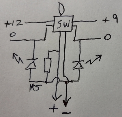
That's the circuit, using a DPDT switch, two LEDs and a 1k5 resistor. I've used two 3mm green LEDs, but you can use whatever is lying around in the scrap box (and there's plenty of stuff lying around in my junk box - not necessarily anything I need but plenty of "junk").
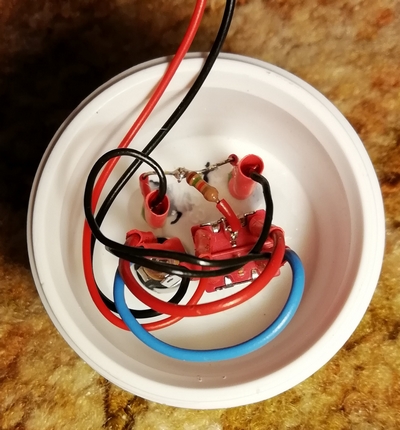
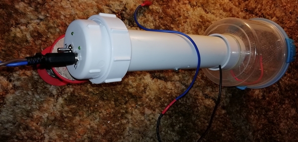
Not much to say about the wiring - the two wires leading off to the top go to the internal 9v battery. The socket, almost hidden to the left of the switch is where the external 12v supply comes in. All that's needed now is the wires to the ion generator (when it arrives!!).
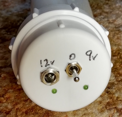
So that's about it for today. The End Cap more-or-less completed and (temporarily) fitted onto the body.
Watch this space for the next installment. If nothing else, cutting the container and it's lid and fitting the mesh - and, maybe, just maybe, the fitting of the ion generator.
Posted

Full Member
Looking forward the the next update when posty arrives.
Gary
__________________________________________________
I am no expert but I do what I can, when I can, with what I can.
__________________________________________________
I am no expert but I do what I can, when I can, with what I can.
Posted
Full Member
While we're waiting for today's post to arrive, I made a start with the container side of things.
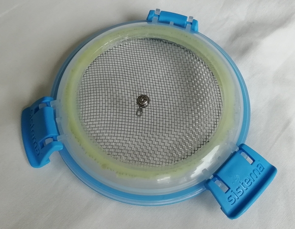
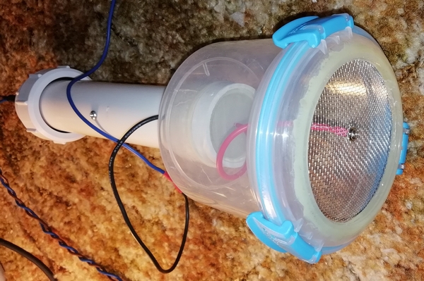
The container lid was the first to feel the wrath of my knife blade. The centre of which was cut out in readiness for the mesh to be fitted over the hole. I thought I'd try to make a solder connection onto the mesh before I went too much further. Not a chance! The solder wouldn't take, no matter how long I held the iron against the mesh. I thought my soldering iron might not be powerful enough. So I tried to attach a magnet to the mesh; even that wouldn't attract - so I guess the mesh is probably aluminium. No worry, it still conducts electricity with very minimal resistance. Therefore, I've made use of a small nut and bolt with a "solder tag" in the centre of the mesh - I'll not be beaten! A pen mark on the mesh gave a good indication of where to cut - but do make it a little larger (10mm or so) so that the mesh overlaps the edge of the hole
After roughing up the inside of the lid with a bit of sandpaper for the glue to take hold against, the circle of mesh was then rapid-set epoxied onto what remained of the lid. Give it a short while and that'll be set and job done.
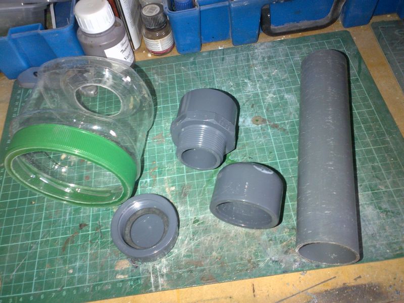
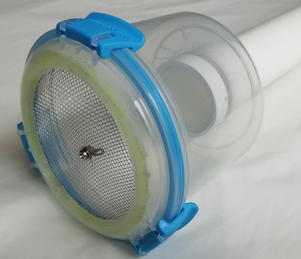
Next up is the container base and the hole that needed to be cut to be a close fit over the pipe (body). A bit more care was needed here as the section taken out needed to be reduced slightly to fit inside the coupler off-cut. Make a mark with a pen around the outside of the pipe and cut a little on the inside of the mark. This is so it can be filed down to ensure a tight fit over the pipe.
The coupler needed to be cut a few mm to one side of the flange half way through its length. An insert of plastic (taken from the cut-out from the container base above) needed to be slightly cut down and made to be a close fit against this flange to prevent the static grass falling back down into the tube. The coupler needed another cut to be made about 10mm away from the first cut.
That's the first four bits to go onto the pipe:
A section of coupler with the flange - about 10mm wide;
A plain section of the coupler - about 20mm but could be cut down a bit further;
The plastic insert to into the coupler with the flange; and
The container base.

The 2nd (plain) off-cut from the coupler goes on the pipe first followed by the container base which is then followed by the section of the coupler with the flange and its now glued in insert. If all these parts fit ok - don't glue them in place yet - push them down to the end of the pipe and make a mark where you will next cut the slot for the ion generator to drop into (when it arrives that it!). The 2nd coupler part will only go down on the pipe as far as the other side of the flange to the blanking off plate.
Nothing here has been glued just yet - I'm really as far as I can go at this stage without the ion generator (the seller has been informed it's overdue!).
As I'm using the smaller of the two 40mm pipes together with the larger coupler, some form of packing will be required to hold the two parts evenly spaced on the pipe - a couple of small pieces of card should do the trick and then the whole lot can be glued once the ion generator has been fitted.
Incidentally, Ian, a small glue gun has been ordered and I would imagine it will do the "glueing" job here just fine.
Now I can sit back, have a cuppa and wait for the postman. Maybe tomorrow.
Posted
Full Member
Ian Lancaster
Please visit my OO Gauge 1930's LMS layout "Jencaster"
http://yourmodelrailway.net/view_topic.php?id=14622&forum_id=21&page=1
Please visit my OO Gauge 1930's LMS layout "Jencaster"
http://yourmodelrailway.net/view_topic.php?id=14622&forum_id=21&page=1
Posted
Full Member
I guess before going too much further, the ion generator ought to be tested. Simply isolate the two HV wires and connect a 12 volt supply to the other (input) wires and see if a spark can be generated when one HV wire is taken close to the other HV wire - only a short test is required simply to prevent a possible burn-out. At 20Kv, a spark of about 1/2inch (12mm) or so should be achievable. Use isolated tools to move the wires close to each other - just in case. Getting hit by 20Kv is not nice! And I'm a bit of a wimp when it comes to voltages of this magnitude!
Not really got the chance to go any further today - fully committed for the rest of today and out with the local walking group tomorrow; so it will be Monday before I go any further with construction.
Suffice it to say, I have given it a quick test (as delivered) and the spark generated was quite healthy. Not only that, but it might also slide inside the pipe given a little filing down of the inside edges against where the corners of the ion generator will slide - either that or the pipe will become distorted.
So it's looking good.
Back soon.
Dave
Posted
Full Member
Been thinking about the unit being "adjustable", 15-20Kv and the tweaking about I did on Friday. There seems to be little information (or none) as to an actual input current at 12v to denote an output voltage - maybe it doesn't quite work this simplistically. The unit as delivered gave a healthy spark with an input current of a little over 200mA. The specification on the web sites give a wattage of 5W. Using an online calculator with an input of 12v and a power of 5W an input current of 416mA was calculated - maybe this is the current is required for a 20Kv output. ????
I did wind the adjustable resistor up to a measured 600mA at 12v - at which point I thought perhaps I ought to stop going any higher. No idea of the size of spark generated. I left well alone at that point. On the calculator the power for this input current came out at 7.2W.
I've tried finding information on how large a gap will a spark jump across in air at a given voltage. What a minefield I'm finding.
One site gave me a minimum and maximum gap for 2Kv - multiply it up by a factor of 10 and it gives a minimum gap of 3mm and a maximum gap of 10.4mm for 20Kv - this being related to the dielectric strength of air at that voltage.
This is definitely loosing me!
I used to have a EHT meter for measuring 25Kv on the back of tv sets - wish I'd kept it. I don't usually throw "anything" away. How useful it would have been now. Maybe it's lurking in a long buried box somewhere in the garage. I certainly can't find it in the array of junk I have rummaged through.
Maybe in the short term I'll wind the pot back down to something like 300mA input current (the calculator gave me a power of 3.6W), and re-start the applicator construction - leaving a small hole in the pipe whereby I could possibly make adjustments at a later date.
Anyone got any thoughts on this? Not the garage and junk, but on input current Vs output voltage for a device such as this.
Cheers
Dave
Posted
Full Member
No further thoughts at this end regarding the voltage generated Vs the input current - so we'll press on regardless and see what happens.
Having seen the ion generator up close and personal (so-to-speak) I note that there is an edge to the undersides of the item and these can be filed down sufficiently to allow it to slide into the pipe with slight restriction and a lack of distorting of the pipe. Very useful. Also, a small 'nick' can be made in the end wall for the positive HV wire to make a more graceful exit from the generator out to the container base and mesh.
The fixing lug at the HV end of the ion generator can also be cut off to allow it to be pushed closer to the container base and thus give a little bit extra length to the HV wire before being soldered onto the container lid mesh.
Once you're happy with the fitting here, remove the ion generator temporarily and the high voltage wires can now be accommodated. Three holes need to be drilled - one for the fixing screw (see below), one for making adjustments to the preset resistor on the ion generator and one for the negative wire to exit the pipe. A hole also needs to be drilled in the blanked off end cap for the positive HV wire.
The ion generator can be held in place inside the tube with a simple screw screwed into the pipe with the end of the screw fitting through the remaining lug on the generator itself. It doesn't have to be totally secure it as it is a moderately tight fit within the pipe; all that's needed is to stop it sliding up and down within the pipe. A small piece of foam can be inserted between it and the blanked off end cap (makes it look a little neater!) and also at the other end for the battery (if fitted).

All prepared, from left to right, the screw cap with the 9v battery lead, the battery itself inside at make-do housing, then ion generator itself with one lug cut off. On the pipe itself there's the securing screw, the hole whereby the small adjustment preset can be accessed next to it and the hole for the negative HV wire further down the pipe.
The negative/earthing wire may need extending to give enough slack for clipping on to the baseboard; the positive HV wire should be amply long enough. Once again, you may find it better to sand down any surfaces where glue will be applied to provide something for the glue to attach itself. Hopefully, the ion generator was tested before being 'fixed' in place.
Slide onto the pipe the pipe off-cut, then the container base and finally the blanked off pipe off-cut. Pull the positive HV wire through its hole in the end cap and glue the end cap onto the pipe ensuring it is a close fit to the end of the pipe itself. Allow the glue to dry here and slide the container base up against the end cap and glue followed by the remaining off-cut pushed tight against the base. Glue in position. Allow this all to dry and set hard. A small blob of glue can be applied to the HV wires to hold them in place and prevent the static grass from getting down inside the device.
Now the positive HV wire can be soldered onto the mesh - or in my case the solder tag; there should be enough slack to allow the container lid to be removed. Now to fit a crocodile clip onto the end of the (lengthened?) negative HV wire and the job is about done.
The 9v battery, in my case, is housed in a coupe of off-cuts of some small cake slices, glued together to make a small pocket. It should be small enough to be a slide fit into the pipe.
The 9v battery lead can now be soldered onto the switch (if not already done) and the ion generator 12v input leads can also be soldered onto the central poles of the switch.
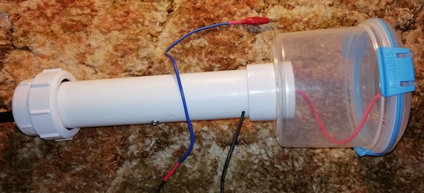
Overall length (excluding any power input plugs and switches) is 315mm - the length of pipe used was 220mm.
Time now for a test to make sure all is working by switching on (obviously) and putting the negative HV wire up towards the mesh. You should be able to draw a spark between the two.
If the container lid/mesh is a bit large for the area to be 'grassed' over, a circle of card can be cutout - with a tight fit into the container body and with a smaller hole cut in it to provide a smaller opening for the grass to fall through. This is then fitted in place after the static grass is put into the container body. Whether this will work, I have no idea - it was something that crossed my mind to try and I see no reason why it won't work.
That's about it for the applicator, all done and dusted. A quick spark test again with both power inputs (looks good) so now to get on with adding the static grass into the container and the layout will never look the same again! That'll be later in the day though.
So, finally, I must say a great thanks to Luke Towan for his idea/design for a Static Grass Applicator that, as always, gets modified to suit local situations and materials (and my ham-fistedness at times).
Happy grassing.
Dave
Posted
Inactive Member
I'm considering and alternative lid that funnels down to a cone with maybe just a half inch diameter hole and wire mesh on the end.
Anyone tried it?
Now I've finally started a model railway…I've inherited another…
Posted
Full Member
My immediate thoughts on this would be rather than soldering the HV wire to the mesh, solder it to a spade connector that could be swapped from the "regular" wide mesh lid to a smaller mesh on an alternative clip-on/screw-on lid.
I see no reason why it wouldn't work.
I did see one video whereby a spade connector was used rather than soldering to the mesh direct or, in my case, to a solder tag and it appeared to work fine. It would just be the obtaining of a suitable (alternative) lid to cut the smaller hole.
Good luck if you try it out. Report back here with your results.
Thanks
Dave
Posted
Full Member
Don't forget to show us the grass.
Posted
Full Member
Yes, it did work (thankfully!) and after a small test - which didn't entirely go well; first off, I think the glue was too 'wet' and the grass just flopped and lay down, then my power supply died on me. After many years of sterling work it had the nerve, the temerity of it, to fail at this very crucial time of my testing. Anyway, switched to 9v battery and carry on.
After a few minutes of finding out why the fuse blew in my PSU, it turned out to be a no longer used 2N3055 having gone short-circuit. A quick snip with the snippers soon had it sorted and a fresh fuse inserted all was well again and a bit more grass was applied (simply as a test of the PSU).
The following couple of pictures show - using neat PVA - how well the 4mm grass has taken to standing to attention.
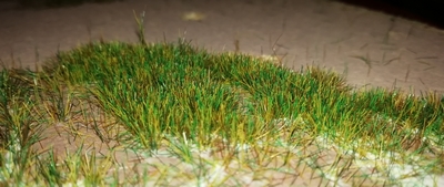
Grass just applied - the PVA is still wet.
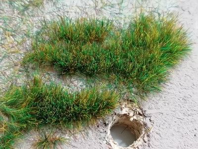
The following morning; the whiteness of the PVA has dried and all looks much better.
So I'm well pleased with it so far.
Now to do a bit more research on what PVA mix is best to use for applying static grass.
Cheers
Dave
Last edit: by Dave C
Posted

Full Member
PVA is a weird beastie, depending on the intended purpose it can be thin (school glue grade) to thick (wood glue grade). I just finished gluing down some squeaky wood tiles this morning, consistency of milk. Must be very special given the price (MSDS says PVA though). My experience with PVA and static applicators is that thicker is better, the vertical fibers stay put. Diluting too far using water or IPA (bit less noxious than methylated alcohol, which can have some funny stuff added) can sometimes give that "rain-trodden" look. Or "cow was sleeping here" patch. OK if that is what was intended, if not it means getting a few cows for the layout. From memory around 90:10 v/v with IPA let the fibers stick upright but kept the surface tension acceptable. That was with carpenters white glue, which is quite viscous. Other grades I know nothing about, although I suspect school grade could probably be used as is.
I think it also depends on how much charge the particles get, and whether you go for low versus high density. Lots of variables.
Any idea how it will function with long (i.e. O scale) static grass (normally 9-12mm long fibers)? I was going to use commercial tufts, but an applicator might be useful.
How long did this take to make?
Nigel
©Nigel C. Phillips
1 guest and 0 members have just viewed this.