Collett Goods 2251
Posted
#251947
(In Topic #13841)
Full Member
Spinning Screw Fixing Body to Chassis
Hello everyone!I picked up a Collett 2251 off E-Bay which runs superbly on DC. I took the body off it to view the options for converting it to DCC (the model is 32-304 2294 GWR Shirtbutton livery) and like the ham-fisted numpty that I sometimes am I put the back screw for fixing the body to the chassis in the front hole.
Now when I try to remove it, the screw rotates in the hole quite happily, but makes no attempt to actually exit said hole! Any thoughts on how to remove it from the collective brains trust?
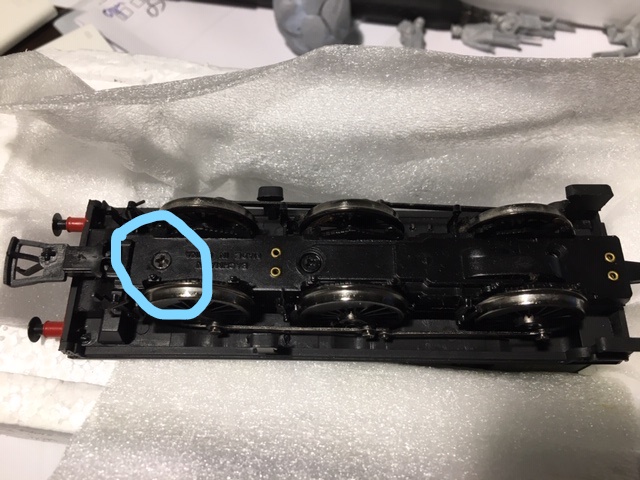
The screw immediately behind the front coupling is the one with the issue. It was actually shorter than the screw that should go in that hole! Have I doomed this locomotive or is the situation retrievable?
It has no decoder socket, but converting to DCC looks straightforward enough. Sound isn't beyond it either, but the speaker and decoder look like they would need to go in the tender - if I could get the body off to wire it up!
Thanks in advance for any advice / suggestions!

Posted

Full Member
It sounds as if it's just that the screw isn't locking onto the threads but won't actually fall out.
You can buy magnetised screwdrivers or, simply rub it against a strong magnetic source for a few seconds and it will pick up enough to hold the screw ………….hopefully !!
Failing that, try a dab of blue-tack on your screwdriver to stick it to the screw.
'Petermac
Posted

Full Member
If all the other screws are out the plate should just lift off. If not, turn right way up and tap. Magnetic screwdriver or magnet. Bluetak. CA glue on the screwdriver (use acetone to separate after). Bottom plates are usually available if you damage it. Worst case you will need to tap a larger hole, or use a self-tapping screw.
Nigel
©Nigel C. Phillips
Posted
Full Member
:doublethumb :cheers
Back on track for fitting a DCC decoder now. Can't thank you enough - I was worried I'd have to do some permanent damage to remove the body.
 Last edit: by Sydney Harbour
Posted
Full Member
'Petermac
Posted
Full Member
Bit of a beauty isn't it?
Any suggestions as to which Kadee to go with? Is it a standard #5?
Last edit: by Sydney Harbour
Posted

Site staff
http://yourmodelrailway.net/view_topic.php?id=8591&forum_id=156
this will give you a good idea on whether you need a standard or off set shank coupler
https://www.kadee.com/coupler.htm
Ron
NCE DCC ; 00 scale UK outline.
NCE DCC ; 00 scale UK outline.
Posted
Full Member
Yes I have the height gauge. Only had it a short time but it has already proved invaluable!
Thanks for the link to the guide page. That will be an enormous help. I can see I will need to experiment….
Posted

Full Member
I replaced a similar Hornby coupling but on a wagon. Just added a photo to the post I did at the time:
http://yourmodelrailway.net/view_topic.php?id=16111&forum_id=21&jump_to=294750#p294750
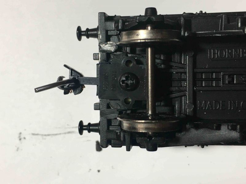
I cut away the peripheral mounts of the old coupling then built a flat base with Milliput. This gave me a reference point to test the positioning for the Kadee #21 box.
The way I've worked out the positioning is to first mount a piece of PS strip 1mm * 10mm wide * 25mm screwed to the desired mounting position so that it protrudes out horizontally from the wagon (loco). Screw the gear box on top of the forward section of the strip and bring it up to your height gauge. It will be positioned far too high - don't worry, measure the amount it is above the top of your reference Kadee.
Next measure the depth of your gearbox, the #21 is 3mm.
If the trial Kadee is 3mm above the desired position vs the gauge, it will be spot on when installed in the desired position. Any variance either way can be managed by either packing out or lowering the mounting surface before installing the gear box.
Posted
Full Member
Cheers Pete.
Posted
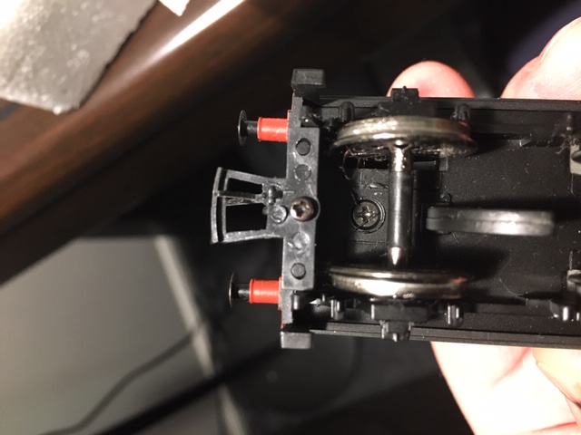
Full Member
Agreed if that works.I think you might be able to remove that screw (tender coupling) chuck the coupling away and then replace the coupling with a Kadee No 19 or even 20 with that same screw. In case of the screw not having enough bite, a spot of appropriate super glue for all plastics will help. I find that putting a 2mm drill through the swallow tail on a Kadee makes it easier to get the screw through without the swallow tail trying to spring it's way back out.
I've no experience of the Hornby 2251 so couldn't suggest that step; you do need to remove all the old gubbins associated with the Coupling mounting before moving forward with the steps I've suggested.
Last edit: by Colin W
Posted
Full Member
If you want KD NEM couplers Peco Dundas have the mounts. You will need the corresponding 362 box from some Bachmann tension hook NEM couplers. KD NEM couplers are underslung. IMO you are better off with metal KD couplers.
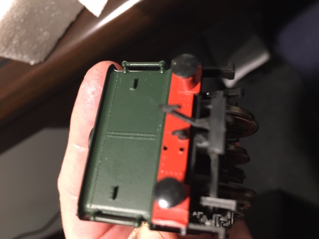
I think you have an older tender mated to a newer engine. My Collette Goods had NEM mounts at either end.
Edit. The middle of the coupler head should be level with the buffer head unless you have very tight curves.
Nigel
©Nigel C. Phillips
Posted
Full Member
- the tender doesn't belong to the Bachmann release (2004) which should have a NEM socket at rear. Even the 1997 release, the earliest in the database had a NEM pocket as far as I can see.
- Could the tender be from some much earlier Bachmann which had the correct union for the loco but an earlier coupling design?
I've found the best way to look up details for non-current models is via this database:
https://www.modelraildatabase.com/classes/details/152/
Then turn to a Google search for your loco with Keywords "Hattons" and "32-304" or whichever code. This will most often turn up a relevant archived Hattons page, even if it's been long out of stock. Handy!
https://www.hattons.co.uk/10171/bachmann_branchline_32_304_class_2251_collett_goods_2294_churchward_tender_in_gwr_shirtbutton_green/stockdetail.aspx
Colin
Posted
Full Member
Colin is right versus the expense re KD NEM couplers. Advantage is that they are unready underslung, and come in 4 !engths, as opposed to the 3 of regular KD couplers.
I gave up going down this route a few years ago.
Wonder what tender is being used. How about a photo? One trick you can use with these tenders is to glue a strip of styrene ~1 mm thick to the underside of the tender where the loco hook goes. Gives much improved coupling distance.
Nigel
©Nigel C. Phillips
Posted
Full Member
It isn't DCC-ready either, which is a shame, but not a surprise. The tender looks the likely option for the decoder plus speaker.
1 guest and 0 members have just viewed this.