Turnout / Point Indication
Posted
#35863
(In Topic #2280)
Guest user
1. Using contacts of a point motor or
2. Using contacts of the toggle switch that operates the motor
A toggle switch that locks on position or the other gives an indication of which way the turnout is set if mounted in a panel suitably labelled.
Push-buttons on the other hand when used with CDU or similar systems normally do not have inbuilt indication so it is the usual practice to have panel indication by either LEDs or GOWs. I prefer LED as these taken less current & generate less heat but either method do require additional contacts on the operating method for analogue control systems.
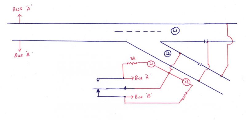
This is where DCC has an advantage. As it is normal that power is on the track at all times, it is now possible to have a LED in series with a resistor ( & I use a 3000 ohms 1/4w unit) connected across the track so that at the frog which has switched power, one LED is alight & the other is shorted out by using the same switch as for frog switching. The drawing below illustrates this principle. The switch in the middle connects the frog to either Bus "A" or "B" and can be either a toggle switch or changeover contacts on the point motor. It has been drawn so that the track is straight through the turnout/point. The 2 LEDs. L1 & L2 would normally be mounted in a panel with the operating switch, either toggle or pushbuttons. The approximate current drawn by each LED is 5mA so even with 50 such indicators, drawing about 250mA - less than one locomotive.
 Last edit: by Sol
Posted

Legacy Member

Posted
Guest user
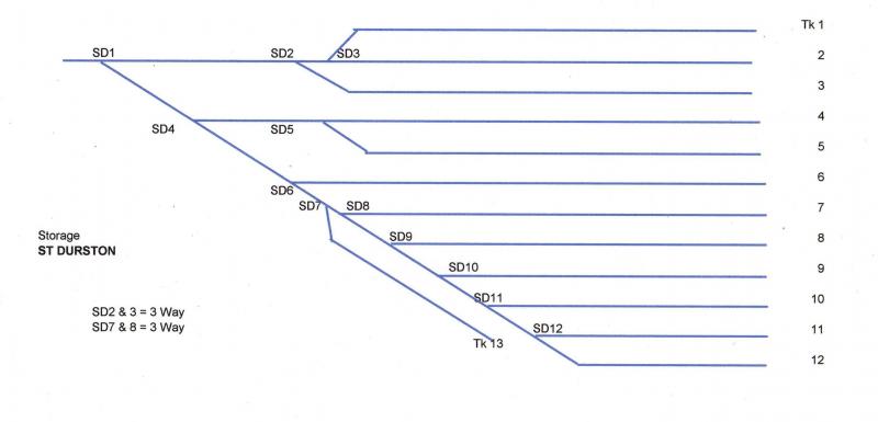
Now that trackwork for the storage sidings has been laid on the D&S, it was the wiring next.
It was my intention to switch all frogs & even though I am using DCC, the storage would be based on analogue practice in that only the track selected would be powered. The DCC convention of providing power on all tracks all the time was not need on these sidings as it is never intended to leave locos with & sounds going unless that train is going to be used.
As the point motors are side-mounted Peco, I need some method of switching frogs & I also want an indication on the panel of the track selected by using LEDs. So for 8 of the 12 points, I use Heathcote Electronics Point Indication Unit with Relay & for the remaining 4, DCCconcepts Ms V2 with his quad relay panel.
Frog switching is easy using the relays on the units but the LED posed a problem.
The circuit I wanted was to have each point motor unit contacts in series with each LED off each to be made contact as per the following.

The DCCconcepts Quad Relay was easy as they are defined changeover contacts but the Heathcote are electronic inbuilt just having two outputs & while it is possible to “series†4 points & then “series†them with another unit, coupling them in series with Quad relays is not possible.
Bummer I thought!!!
Initially I thought I was going to have to provide another 12 relays, worked by the contact on Heathcote & Quad relays to give me more contacts & I was not looking forward to do this (even though I had plenty of 50v DC relays) then I remembered the Thread I started months ago.
Tried it again & lo & behold, all worked.
The LED switches off & on by the action of point motor & frog switching.
I contacted Richard Johnson of DCCconcepts & discussed any possible problems.
The only problem was additional wiring – instead of one wire from relay to LED, it is now 2 wires per LED from track but in fact for two tracks from the same point, 3 wires is all that is needed.

Because DCC power is basically AC, the LED only conducts one way but it does not flicker due to the high frequnecy of DCC power. Normally LEDs may not like AC so too protect it, insert either in series or across the LED, another convential diode, poled correctly to either block the AC one way or bypass it the other. I think the cost per track would be under $1 ( 50p).
This circuit as used on my storage means that at any one time, only one LED is alight so a drain of 20mA maximum on the DCC power but even if the tracks were wired to DCC convention in all tracks powered, wiring via the frog as per Post #1 overcomes most concerns but then all points have an indication of setting - not what I was after.
Posted

Site staff
Ron
NCE DCC ; 00 scale UK outline.
NCE DCC ; 00 scale UK outline.
Posted

Full Member
all the best. Kevin
Staying on the thread Kevin.
Posted
Site staff
Now this post of yours Kevin - you have lost me as I cannot see how it relates to the thread ?Hi Ron. Having a dozen or so Locos ( with diesel sound) in use at the same .time would be quite deafening. Unless you lived in a lonely spot, I could well imagine that your neighbours would kick up a fuss.Neighbours, take mine, please, according to her she told one housing officer that I was a squatter, and then when a new housing officer came along she complained about my "grand kids" running up and down in the lift/elevator all day. The truth of it is I have a tenancy agreement and I never had any children let alone grandchildren .
all the best. Kevin
Ron
NCE DCC ; 00 scale UK outline.
NCE DCC ; 00 scale UK outline.
Posted
Full Member
Staying on the thread Kevin.
1 guest and 0 members have just viewed this.