LED route indication
Posted
#247287
(In Topic #13658)

Full Member
I have a new section of baseboards carrying my storage roads - 2 in each direction (up line and down line) with crossovers mid way thus allowing either 2 short trains or 1 long to be stored on each road. The 3rd track on each side is the through route. i.e. I have 6 tracks in total - 3 "up" and 3 "down".
As the whole of this area will be covered by a high level board, I want to build a mimic panel using LED's to show which route is set.
Ideally, I'd like to use my Lenz LS150's to control the Tortoise point motors. Tabs 1; 2; 3; 4 and 8 will be used for the motor and frog polarity. This leaves the other internal switch (tabs 5; 6 and 7) for the LED route indicators.
I've watched videos etc. of Tortoise/LED route indication until I look like a tortoise but they all seem to use DPDT switches and bi-colour LED's.
Is it not possible to use this spare internal switch to power the LED's directly - i.e. without the DPDT switch and furthermore, could I light up just 1 green LED showing which route is set ? By that, I mean both the through track and the turn has a single green LED on the panel and, depending on which way the Tortoise is set, one or the other lights up ? It's obvious to me that, if the "open" route is showing green, the other would be unavailable (red) without actually having to signal it as thus.
It could be that, as with the frog tab "4", only tab "7" is available for output, in which case, only one green LED could be wired. Bi-colour ones, used in pairs, would presumably show either red or green depending on which way the current ran through them ……………… :hmm
A final question - for now anyway - I've read that, if powered through the Tortoise switch, the LED's don't need a resistor because the Tortoise already acts as one. Is this true ?
Sorry it's so long winded but I'm not at home and am slightly bored not being able to get at the actual layout ………..
'Petermac

Posted

Site staff
Ideally, I'd like to use my Lenz LS150's to control the Tortoise point motors. Tabs 1; 2; 3; 4 and 8 will be used for the motor and frog polarity. This leaves the other internal switch (tabs 5; 6 and 7) for the LED route indicators. Yep, go for that - both internal switches are SPDT completely separate from each other
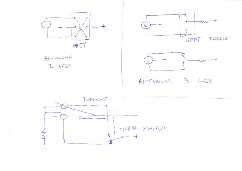
I've watched videos etc. of Tortoise/LED route indication until I look like a tortoise but they all seem to use DPDT switches and bi-colour LED's. Bi-colour LEDs can be either 3 legged switched via SPDT or 2 legs switched via DPDT
Is it not possible to use this spare internal switch to power the LED's directly - i.e. without the DPDT switch and furthermore, could I light up just 1 green LED showing which route is set ? By that, I mean both the through track and the turn has a single green LED on the panel and, depending on which way the Tortoise is set, one or the other lights up ? It's obvious to me that, if the "open" route is showing green, the other would be unavailable (red) without actually having to signal it as thus. Yep
It could be that, as with the frog tab "4", only tab "7" is available for output, in which case, only one green LED could be wired. Bi-colour ones, used in pairs, would presumably show either red or green depending on which way the current ran through them ……………… :hmm
A final question - for now anyway - I've read that, if powered through the Tortoise switch, the LED's don't need a resistor because the Tortoise already acts as one. Is this true ? Yep as per instructions that come with the Tortoise
Now I am away soon for the day but later i will do some drawings and post them here but this site has lotsa info
Untitled Page
Ron
NCE DCC ; 00 scale UK outline.
NCE DCC ; 00 scale UK outline.
Posted
Site staff
Ron
NCE DCC ; 00 scale UK outline.
NCE DCC ; 00 scale UK outline.
Posted
Site staff
the scribble on the LHS toggle is DPDT
Ron
NCE DCC ; 00 scale UK outline.
NCE DCC ; 00 scale UK outline.
Posted
Full Member
I'll check out the index and also have a good read of Brian Lambert - if only to see how quickly I get lost …………… :roll: :roll:
'Petermac
Posted
Site staff
https://www.dccconcepts.com/manual/leds-and-how-to-get-the-best-from-them/
Ron
NCE DCC ; 00 scale UK outline.
NCE DCC ; 00 scale UK outline.
Posted
Full Member
I'm in the process of fitting Tortoise motors to my fiddle/storage yard.
This section will be controlled by DPDT switches incorporating LED route indicators on a mimic panel.
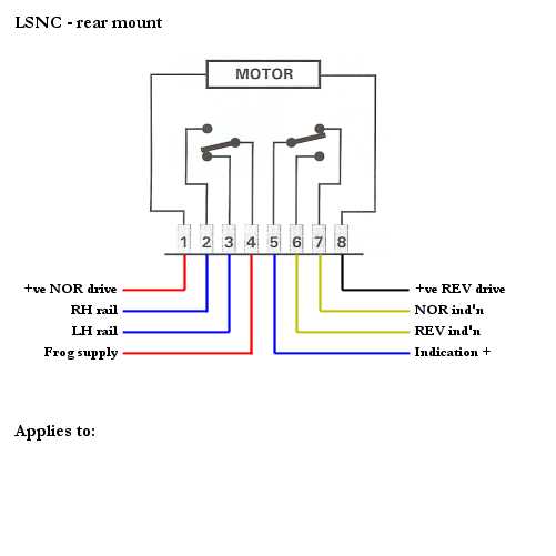
The Tortoi have 8 outputs.
1 & 8 will be connected to a dedicated 12v transformer, 2 & 3 are connected to the track and 4 to the frog.
This leaves 5, 6 & 7 for the LED indicators. I'm guessing No 5 is connected to the LED but where do the remaining contacts go and where do they get their power from - do I need another transformer or are they already powered internally by the Tortoise ?
'Petermac
Posted
Site staff
Along with Doug, Worzels got 'is confused head on ………………………
I'm in the process of fitting Tortoise motors to my fiddle/storage yard.
This section will be controlled by DPDT switches incorporating LED route indicators on a mimic panel.
The Tortoi have 8 outputs.
1 & 8 will be connected to a dedicated 12v transformer, 2 & 3 are connected to the track and 4 to the frog.
This leaves 5, 6 & 7 for the LED indicators. I'm guessing No 5 is connected to the LED but where do the remaining contacts go and where do they get their power from - do I need another transformer or are they already powered internally by the Tortoise ? NO , they are completely separate from the operating circuitry of the unit
Peter, I will do a drawing tomorrow.
but have a look at these first
(Click to enlarge)
(Click to enlarge)
Ron
NCE DCC ; 00 scale UK outline.
NCE DCC ; 00 scale UK outline.
Posted
Full Member
Maybe using the LS150's offers some advantage beyond just controlling the points afterall.
'Petermac
Posted
Site staff
Thanks Sol - it seems I'll need 2 transformers in that case - 1 to power the motors and another for the LED circuit ………………………..
Maybe using the LS150's offers some advantage beyond just controlling the points afterall.
No - one 9 or 12 v DC output will do both - drawing will come in about one hour after I have had breakfast.
Ron
NCE DCC ; 00 scale UK outline.
NCE DCC ; 00 scale UK outline.
Posted
Site staff
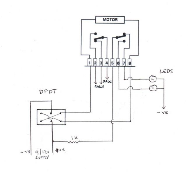
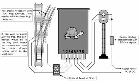
Fig 4 of the Tortoise info attached is the easiest I think.
Ron
NCE DCC ; 00 scale UK outline.
NCE DCC ; 00 scale UK outline.
Posted
Full Member
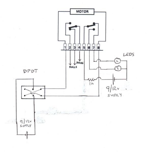
Peter, this is just of many ways of having LEDs for route indication using the same power supply as the operating circuit.
Fig 4 of the Tortoise info attached is the easiest I think.
Thanks for this Sol.
I'm still slightly (??) in the dark !!
Given that the Tortoise is able to power LED's without the need for a resistor, why have you put one in the +ve wire feeding terminal 5 ?
Also, from your drawing, it looks as if you've shown 2 LEDs - a red and a green (?). I only want to use a single green showing which route is "open". Would I wire 2 x greens (1 on each route) with the short leg on one soldered to the short leg on the other ?
Furthermore, would I connect the -ve from the LEDs to the -ve on the DPDT switch ?
'Petermac
Posted

Full Member
Nigel
©Nigel C. Phillips
Posted
Full Member
'Petermac
Posted
Site staff
Yes, both -ve's are the same - I drew it that way assuming it was self evident it meant the same power source - saves drawing another long connection.
The resistor is needed for the LED's in this case but not when used as per Fig 4 of the Tortoise instruction - those are in series with the Tortoise motor which acts as the resistor in that case.
Use what ever colour LEDs that you want - each one represents one leg of the turnout . Yes the short leg connections are to the -ve supply.
The LED circuit I provided is not connected to the Tortoise operate circuit in any way except for the common power supply.
Ron
NCE DCC ; 00 scale UK outline.
NCE DCC ; 00 scale UK outline.
Posted
Site staff
It may show two supplies ( either 9 or 12 v - 9 volt makes Tortoise quieter ) but that is then upto the user.
this old circuit from one such relay set in old telephone exchanges shows many supplies but in fact is just one supply for the entire exchange
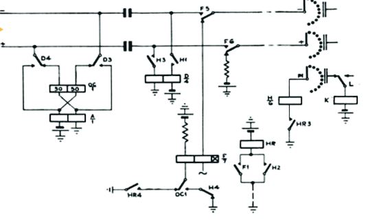
for explanation of the symbols for power.
Circuit Symbols | Electronics Club
Circuit Diagrams | Electronics Club
Ron
NCE DCC ; 00 scale UK outline.
NCE DCC ; 00 scale UK outline.
Posted
Full Member
Wot 'e sed. Contacts for the 2 internal; switches are independent of the motor supply, so you could rig a signal to one set and the frog to the other set, or in this case as Ron did one to the frog (using track power) and the other making a circuit for the LEDs (using a separate DC circuit). If you have a lot of LEDs you may need a bigger power source.
All depends on how many you want to run. Keeping the wiring and power supplies separate is actually not a bad idea.
Nigel
©Nigel C. Phillips
Posted
Full Member
Thanks for the clarification about the resistor Sol - I think I'll leave you to digest the details of the telephone exchange - an on/off switch challenges me ……………!!!
When I mentioned the LED short legs, I think I read somewhere that if you daisy-chain a pair of LEDs - long leg - short leg - short leg - long leg, when you feed power in one direction, one will light whilst the other doesn't and fed in the other direction, the other LED lights whilst the first will be off. Not sure I've explained that very well but I know what I mean …………………….

'Petermac
Posted
Site staff
Ron
NCE DCC ; 00 scale UK outline.
NCE DCC ; 00 scale UK outline.
Posted
Full Member
Switches:
Do I need to use DPDT switches or would SPST do the same job ?
On - On are what I need I think - i.e. no centre "off" position.
Where would one buy these switches (European readers only ……) ? I have a few of each (DP and SP) in stock but, when I looked at current prices, I gulped !!!
I'm still not comitted to this system of control and do have my LS150's in reserve ………………………cost-wise, that might be the better way to go. Presumably I could still have route indication although, as I said at the start, physically having to throw a switch would avoid possible memory failures via an accessory decoder ……………………… :hmm
'Petermac
1 guest and 0 members have just viewed this.