Electrics DCC
Posted
#229666
(In Topic #12553)

Full Member
What happens to NCE Powercab output in programme track mode
Hi All. I have read different reports about the two wire output of the NCE Powercab . And a lot of criticism which I don't understand , but I do have a question . When the Powercab is in programme track mode, it is said to be safe with Decoders , my question being "I have a programme track wired to a centre off toggle switch, but what makes the Powercab programme track any different from the main?" The NCE manual give two diagrams for wiring the programme track, one with their dedicated switch, and one with a centre off toggle switch. And where is the " Safer" element with the same two wires? All the best. Kevin
Staying on the thread Kevin.

Posted

Site staff
Ron
NCE DCC ; 00 scale UK outline.
NCE DCC ; 00 scale UK outline.
Posted
Full Member
Staying on the thread Kevin.
Posted

Full Member
Another OWT. Older decoders such as those from Digitrax need higher voltages to be read. Often with an NCE system you get "CV unreadable". You can still program the decoder. Digital sell a booster so that the cv's can be read. Digitrax systems have a higher voltage for programming.
Nigel
©Nigel C. Phillips
Posted
Full Member
Staying on the thread Kevin.
Posted
Full Member
I suspect most DCC users don't change anything from out of the box. The one that's worth getting to know is CV29. A lot of things you do with the controller are changing CVs on the fly, it's all in the background.
Nigel
©Nigel C. Phillips
Posted
Full Member
Staying on the thread Kevin.
Posted

Inactive Member
Just work out the value you want, then put that in.
Max
Port Elderley
Port Elderley
Posted
Inactive Member
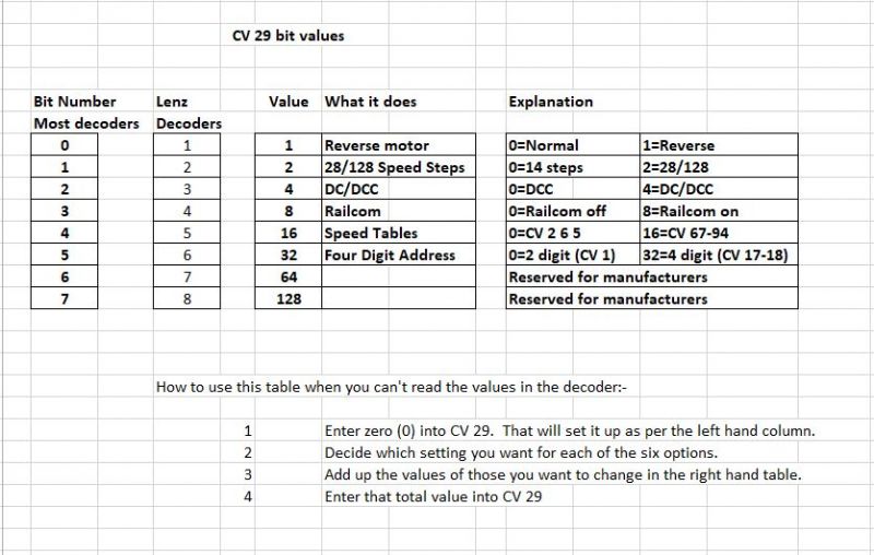
CV 29 – bits and pieces
By Max Wright MMR 578
For those of us “old school†DCC zealots (I never thought DCC and old school zealots would be together in a phrase), who remember life before the automated CV 29 converters; perhaps a word about the bits of CV 29.
There are still some decoders which resist the auto CV 29 converters, (Lenz decoders being one of them, as we will see shortly) and of course, there are still those of us who steadfastly stick to our Lenz systems.
Lenz has appeal to me for their ability to supply a contiguous chain of hardware for use in computer control, where other brands need off grid bolt on stuff; but I digress.
CV 29 uses 8 subdivisions, or bits for control of some critical functions of motion decoders. In most decoders the bits are numbered 0 to 7, while in Lenz they are numbered 1 to 8.
This numbering disparity doesn’t really affect the programming, as the bit value refers to the function you are trying to change, or vary – hence the thing we use to personalize our decoders (vary the configuration of), is called a Configuration Variable or CV.
In daily use, there are 6 bits of CV 29 which we use for basic control, viz:-
· Motor direction; forward or reverse.
· 14 or 28/128 speed steps.
· DCC or DCC/DC
· Railcom on or off
· Use of speed tables (CV 67 to 94) or three step settings (CV 2 6 and 5).
· 2 digit addresses 1 to 127 (CV 1); or 4 + digit address 128 > (CV 17 and 18).
It’s NOT possible to change one bit by itself. Each time we want to change a bit, the total values of all of the bit integers must be re-entered.
Here’s a table which shows us what we need . . .
So, if a decoder has a value of zero for CV 29, then the motor will go forward, the throttle will be 14 steps, DC will be off, Railcom will be off, the three step control will be on and the loco will only be able to have a two digit address. Perversely 2 digit addresses go up to 127.
Now, if we want the motor to go forward when we select forward on the throttle (0), we want to use 128 speed steps (2), DCC only (0), Railcom to be off (0), a speed table (16) and a 4 digit address (32); if we add 2 + 16 + 32 = 50 – that’s the number to enter into CV 29 to make those three changes happen.
If we decide later to only use CV’s 2 6 and 5 for speed control, then the value for the speed table (16), is subtracted from the 50, becoming 34 which is the integer entered into CV 29.
Simple, yes?
For those who have got this far and now have a migraine, I’ve attached a chart with explanation, which will solve every problem.
Just set CV 29 to 0.
Add up the integer values for the combination of facilities you desire and enter them into CV 29.
Happy Throttling.
Max
Max
Port Elderley
Port Elderley
Posted
Full Member
All the best. Kevin
Staying on the thread Kevin.
Posted
Inactive Member
There are other CV's which are more used for fine tuning, and which don't need a programming track.
CV 2 = Start Voltage
CV 6 = Mid Speed; and
CV 5 = Full Speed
These three CV's will give you enough adjustment to make your loco run well - and they can be varied on the main track - in some cases while the loco is moving.
CV 2 Keep reducing the value of CV 2 until the loco just begins to move when you select Throttle Step 1.
CV 5 Keep adjusting the value until the loco runs at a believable speed with the throttle fully open.
Then . . .
CV 6 Adjust the value of CV 6 so that it is midway between the values you entered into CV's 2 and 5.
Now that's about as simple as it can get. :cool:
Max
Port Elderley
Port Elderley
Posted
Site staff
If you don't get the results you like, just change them.
All one has to do is to RT.M ( read the… manual)
Ron
NCE DCC ; 00 scale UK outline.
NCE DCC ; 00 scale UK outline.
Posted
Site staff
DCC is just another aspect of the hobby.
Ron
NCE DCC ; 00 scale UK outline.
NCE DCC ; 00 scale UK outline.
Posted
Full Member
Staying on the thread Kevin.
1 guest and 0 members have just viewed this.