Wiring Peco code 75 3Way points using TORTISE motors, toggle switches with LED's om control panel
Posted
#246667
(In Topic #13617)
Full Member
I have wiring diagrams showing the use of DPDT switches for each motor (ie X 2) and incorporating LED's as route markers but nothing specific for using one switch without using complicated relays. (If possible ???) or how to wire for the cross over situation.
Hope I haven't confused everyone with my plight ??
Any assistance would be most appreciated.
BigMac

Posted

Site staff
Ron
NCE DCC ; 00 scale UK outline.
NCE DCC ; 00 scale UK outline.
Posted

Full Member
Nigel
Edit: You can also also ditch the Peco wiring, convert to all-powered rail, isolated frogs, and use frog juicers to change frog polarity. Lot more complicated.
©Nigel C. Phillips
Posted
Full Member
For ordinary points, you can wire leds in series with the Tortoise motors as the motor acts as a resistor. No need for a separate circuit.
Cheers Pete.
Posted

Full Member
 Last edit: by Passed Driver
Staying on the thread Kevin.
Posted

Full Member
A three-way turnout will always require 2 switches, whether in separate units or combined into a rotary.
The use of relays is something I am employing to do several jobs at once. The switch on the turnout motor is fed with a low voltage supply (12volt is fine) and as the motor moves, it toggles between turning the relay prime circuit on or off.
Think of a lift call button lighting a light and triggering the lift electronics to come and collect you. The button, its light, the electronics and the lift motor are all separate. The relay has the added bonus that the button is not connected to the lift motor circuits for safety!!
An 8-pin relay will give you a primary circuit (turning it on or off = 2 pins) and then 2 clusters of 3 pins offering 2 separate switches. One can be used to change frog polarity and other can be used as part of an LED circuit for your mimic panel. Note that the primary and secondary circuits are ALL independant so can be used as described. The only link is a magnetic one insofaras the primary circuit changes the attitudes of the secondary switches.
11-pin and bigger are available (but progressively more expensive) if you need to have 3 or 4 independant switches doing things.
I sourced my relays from China at about £1.50 each including postage via eBay.. The key factors are (1) the voltage rating of the primary circuit [many big ones are 240volt] and (2) the power rating of the secondary circuits. Mine are rated at 12volt primary side and 5Amp secondary (which I am not going to get anywhere near).
I am stacking my relays in the storage area to show which track is selected from the ladder of sidings available. If required, I can post a circuit diagram showing how I plan to do it.
Please note that I am not an electronics wiz and accept that brighter minds than mine will have come up with neater, simpler ways of doing this, perhaps involving some other electronic gizmo!
Barry
Shed dweller, Softie Southerner and Meglomaniac
Posted

Full Member
Yes please Barry,Hi BigMac
A three-way turnout will always require 2 switches, whether in separate units or combined into a rotary.
The use of relays is something I am employing to do several jobs at once. The switch on the turnout motor is fed with a low voltage supply (12volt is fine) and as the motor moves, it toggles between turning the relay prime circuit on or off…………………………………………………
I am stacking my relays in the storage area to show which track is selected from the ladder of sidings available. If required, I can post a circuit diagram showing how I plan to do it.
Please note that I am not an electronics wiz and accept that brighter minds than mine will have come up with neater, simpler ways of doing this, perhaps involving some other electronic gizmo!
Barry
This is something I need to understand for my future plans.
Colin
Last edit: by Colin W
Posted
Full Member
Hope this makes sense. The box and upright contacts beside each point motor represents an 8-pin relay. The box is the primary circuit, switched on and off by the turnout motor switch (the red circuit). The green circuit is for the LEDs with its own low amp supply. This wiring layout means that only one LED will be alight at any one time showing the road that is set. I will replicate this at the other end of the running loops to give me confirmation that both ends are set for the same road!! The unused pins on the relay will be wired to change the point frog polarity but I left those wires off this diagram for clarity. If you are using dead frogs, a 5-pin relay will do the job whereas if you wanted more functions, you could use an 11-pin relay - same idea just bigger.
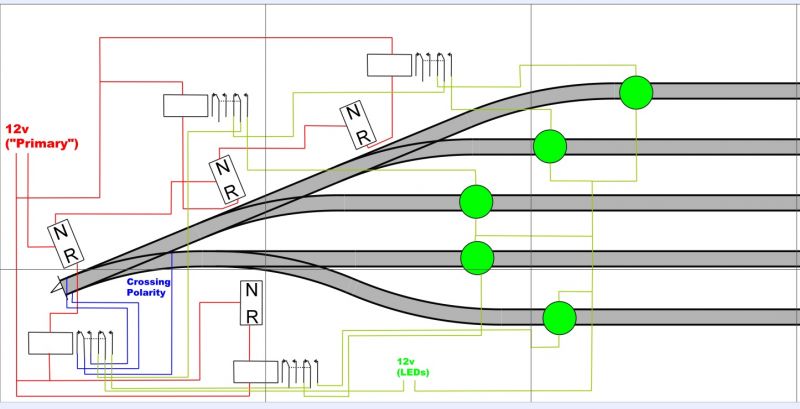

These are the relays I am using - but 12volt versions. Bought from eBay. Search "Mini Power Relays 12 volt 8-pin". I bought 40 post-free for under £1 each.
Barry
Shed dweller, Softie Southerner and Meglomaniac
Posted
Full Member
Staying on the thread Kevin.
1 guest and 0 members have just viewed this.