Wiring for North American pick-up
Posted
#212526
(In Topic #11601)

Full Member
Adding wipers
Hi all,This is applicable for both DC and DCC (especially DCC). North American steam locomotives (not the 12" to the foot ones) usually have engine pick-up on one side, tender pick-up on the other, achieved by using live axles and one insulated wheel. This means that the engine chassis is live (as is the tender chassis) and the motor may even be wired directly through one of the brushes via the open-frame motor housing*. This arrangement is also found on older UK models, especially those with tender drive or die-cast chassis'. I have less than tender memories of an old SE Finecast Collett Goods white metal monstrosity (I hesitate to say kit) with an old Hornby chassis, Paxolin board and wiveted wipers and "North American" pick-up. I could never figure out why the previous owner had put wipers on the same side as the live axles. Much lurching down the track accompanied by copious sparks. "Good runner" said the seller. Referring to himself of course, with my money. I did keep the Romfords that it came with, the rest of it is making itself useful as weights in freight cars.
Many of us are familiar with adding pick-ups to either tenders or engines, some of us are not, and may find the following useful. I'm planning on adding some additional pick-ups to a Japanese brass model of a Great Northern Pacific locomotive that has engine and tender pick-ups on opposite sides. Luckily the motor on this model was isolated, and for an open-frame design efficient. Life is a bit more complicated as the body of the engine and the body of the tender are also live. It runs perfectly in DC and DCC mode, but long dead frogs (bless them one and all) on #8 or #10 turnouts can bring this locomotive to an untimely halt. I belong to a modular HO group, not everybody keeps frogs as short as possible or even live. I'll also be addressing pick-ups on the tender wheels as well, but not with wheel tread wipers (sorry Nick).
The picture below shows the underneath of the engine, and where I'm planning on putting the copper-clad boards and phosphor bronze wipers. I'm still debating whether to use sprung plunger pick-ups mounted in small sections of angle brass fixed to the chassis inboard of the wheels. Basic idea is the same. I'll do some mock-ups and make a decision. Aim of course is to make it as invisible as possible without damaging the brass work. More to follow as progress is made. Now where are those AGW plunger pick-ups? The 2-56 tap? Come to think of it, the rest of my trains? Ah, the joys of moving and downsizing……..
Nigel
*The motor must be isolated for DCC operation.
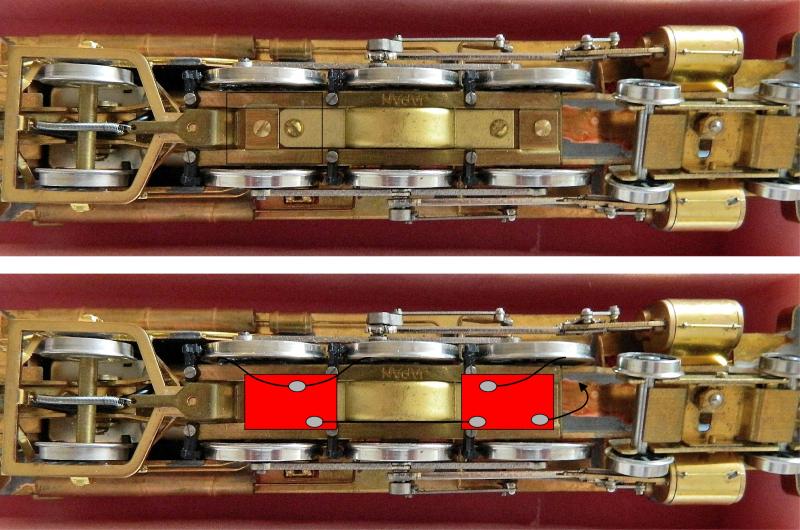
Copper clad in, well, copper. Wipers in black would be 15 thou' PB wire. Grey blobs solder. I guarantee it will not be as neat as this. I may well combine the 2 copper clad pieces and just have one small board to the side of the central gear housing. Bit tight but doable. Arrow to the motor. That's the plan…..
©Nigel C. Phillips

1 guest and 0 members have just viewed this.