Kickback diodes
Posted
#233875
(In Topic #12825)
Full Member
I have read different opinions on this and just wondered what other people thought.
I am using 30V 10A (DC) relays to control the seep points using a CDU.
I am reading conflicting advice as to whether diodes are needed to protect the switch (in my case the relay) from the reflected current.
Have people used diodes for this? And does it make any difference?
Many thanks for your help.

Posted

Site staff
This concept of protecting contacts was used a lot in LM Ericcson Crossbar telephone exchanges using a small value capacitor & resistor.
Ron
NCE DCC ; 00 scale UK outline.
NCE DCC ; 00 scale UK outline.
Posted
Full Member
What rating diodes do you use?
Posted
Site staff
Ron
NCE DCC ; 00 scale UK outline.
NCE DCC ; 00 scale UK outline.
Posted
Full Member
Posted
Site staff
has a transistor in the operate path , once the connection between CDU & solenoid is made, keeps the input voltage to the CDU switched off so that when the solenoid operate switch is released, there is only a very small current flowing flowing through the switch so it doesn't burnout under high current. Then the CDU recharges ASAP if not faster.
I am not sure how you intend to use the relay to operate the CDU output though - have you a circuit you can post?
Ron
NCE DCC ; 00 scale UK outline.
NCE DCC ; 00 scale UK outline.
Posted
Full Member
this is the simplied diagram with mot exact example of the switched but they are of the correct type.
This is the relay board i use:

Posted
Site staff
(Click to enlarge)
or

(Click to enlarge)
Ron
NCE DCC ; 00 scale UK outline.
NCE DCC ; 00 scale UK outline.
Posted
Full Member
Basically, the track is the Hornby track pack layout:
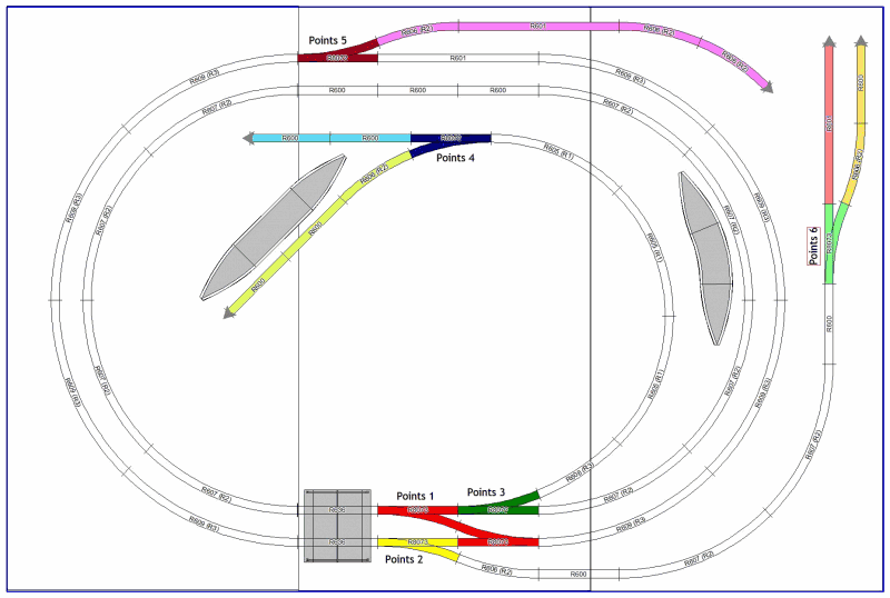
There are point motors at each of the points. So 6 in total (two points throw in tandem)
The relay also controls power to the 6 sidings so they can be isolated.
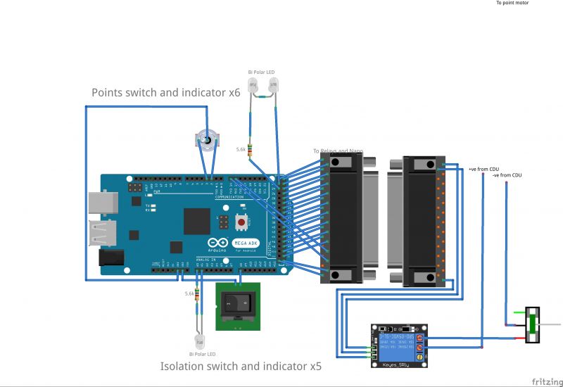
when the switch is thrown it sends a signal to the Arduino board that then sends a signal to the relay via a 5v trigger. this is on a different board connected via a 22way cable.
The Arduino closes the relay for 10ms and then reopens it, which is long enough to throw the point.
The +ve from the CDU is connected to twelve of the commons on the relay and the -ve is connected to all the common returns of the point motors.
The relay is then connected to each side of the point motors, so one point motor needs 2 relays, one for each direction of the point. The NO output from the relay connects to one side of the point motor. closing the relay completes the CDU circuit to throw the point.
The relay board can be found here
 Last edit: by Jon Miles
1 guest and 0 members have just viewed this.