Help required with wiring
Posted
#247692
(In Topic #13674)

Full Member
[Wurzel's got 'is Muddled 'Ead on]
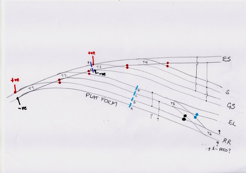
Herewith the track plan of my D.C.layout, with Engine Shed line, Siding, Goods Shed line, End Loading and Run Round.Red dots show existing rail gaps.
All turnouts are live frog, switched from the slide switches which operate the wire-in-tube system.
Currently, ES, S, and GS are wired as shown with rail breaks at F & E and all 3 tracks work fine, fed from F & E, a small 0-4-0 locomotive passing smoothly backwards and forwards over the turnouts.
The run round loop and the end loading spur have now been installed and I have got myself rather muddled and I can't remember how I did it last time!
1. Do I need to make rail gaps at A,B,C and D as shown
2. Will I have to connect feeds at the right hand side near letters RR,
3. Will I have to additionally gap the turn out frog rails as shown by the blue and black dots at the lower right?
4. Are my links to the right of A,B,C and D necessary?
What else have I missed?
I'd greatly appreciate some help with the above,
Douglas Wurzle
'You may share the labours of the great, but you will not share the spoil…' Aesop's Fables
"Beer is proof that God loves us and wants us to be happy" - Benjamin Franklin
In the land of the slap-dash and implausible, mediocrity is king
"Beer is proof that God loves us and wants us to be happy" - Benjamin Franklin
In the land of the slap-dash and implausible, mediocrity is king

Posted

Site staff
one controller only ?
one loco on the layout ?- if two on the layout. how were you going to isolate one while the other is chuffing around ?
You don't need dotted connection s ? nor blue insulators A, C & D
Yes to your point 2. Will I have to connect feeds at the right hand side near letters RR
Don't need blus dot on the EL rail but certainly the blue dot on the rail tween T5 & T6.
I will be away this AM but when I come back in a few hours & you may have replied, I will modify your drawing .
Ron
NCE DCC ; 00 scale UK outline.
NCE DCC ; 00 scale UK outline.
Posted
Full Member
Thank you for replying, to answer your questions..I have a double track controller, I'd use one channel for the teminus and the other channel to power the route round the room to the other terminus, with some sort of switching.
This is a 1950 terminus to terminus layout, the other station will be on the other side of the room. a railcar and a 14xx with autocoach for passengers and something to move goods [I have an early crest Beattie well-tank]. I intend having an isolating switch for the shed road and end loading spur and the left hand end of the platform road.
The breaks at E & F are only there at present because I laid the engine shed and siding track first, ideally I'd like to have just two feeds at RR and the toe of T1.
Hope this makes sense, looking forward to your reply,
Chubber
'You may share the labours of the great, but you will not share the spoil…' Aesop's Fables
"Beer is proof that God loves us and wants us to be happy" - Benjamin Franklin
In the land of the slap-dash and implausible, mediocrity is king
"Beer is proof that God loves us and wants us to be happy" - Benjamin Franklin
In the land of the slap-dash and implausible, mediocrity is king
Posted
Full Member
Are you using a Gaugemaster or a H&M controller? Gaugemasters allow for common rail wiring whereas the H&M or other types do not necessarily follow. The upshot is you MAY need insulators on each area on both rails but I would not like to say without your further input.
We have had a similar discussion on a terminus to terminus layout http://yourmodelrailway.net/view_topic.php?id=15213&forum_id=6 which is possibly not much different to your own set up in a schematic sense anyway. Perhaps full layout diagram (even if it is not finalised) would be helpful … the wiring diagrams are easy and I should be able to make one quickly enough to be of help to you,
Cheers
Trevor
Posted
Site staff
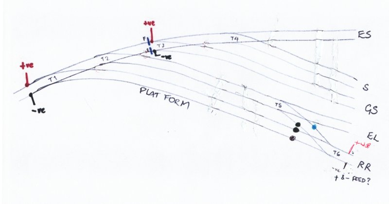
I have removed a lot of insulators near frogs as you are frog switching so feeding power down the tracks required
IE middle feed at T2 will serve GS track or T4 turnout which will feed either ES or S
I added a insulator at T6 just in case your controllers do not allow common rail as Trevor has mentioned.
Each frog gets it power from adjacent stock rails via the microswitch.
Ron
NCE DCC ; 00 scale UK outline.
NCE DCC ; 00 scale UK outline.
Posted
Full Member
Hullo, Trevor, I am using a Gaugemaster DS two channel controller with simulated breaking. Thank you for your input, the 'other end' will one day be a 'Minories' type station with the current terminus accessing it on a bay platform. At my current rate of progress, Network Rail will be running 'Levitron' trains before it's completed!Hi Doug,
Are you using a Gaugemaster or a H&M controller?
Trevor
Douglas
'You may share the labours of the great, but you will not share the spoil…' Aesop's Fables
"Beer is proof that God loves us and wants us to be happy" - Benjamin Franklin
In the land of the slap-dash and implausible, mediocrity is king
"Beer is proof that God loves us and wants us to be happy" - Benjamin Franklin
In the land of the slap-dash and implausible, mediocrity is king
Posted
Full Member
Thank you, Sol, succinct and helpful as usual. With a Gaugemaster controller I should be O.K. so I'll have a go and see what happens. How I miss the old Hornby Dublo controller that went 'Buzzzzz' and a button popped up in the event of a short, etc.!Here is my thoughts
I have removed a lot of insulators near frogs as you are frog switching so feeding power down the tracks required
IE middle feed at T2 will serve GS track or T4 turnout which will feed either ES or S
I added a insulator at T6 just in case your controllers do not allow common rail as Trevor has mentioned.
Each frog gets it power from adjacent stock rails via the microswitch.
Douglas [Less Wurzelled now]
'You may share the labours of the great, but you will not share the spoil…' Aesop's Fables
"Beer is proof that God loves us and wants us to be happy" - Benjamin Franklin
In the land of the slap-dash and implausible, mediocrity is king
"Beer is proof that God loves us and wants us to be happy" - Benjamin Franklin
In the land of the slap-dash and implausible, mediocrity is king
Posted
Full Member
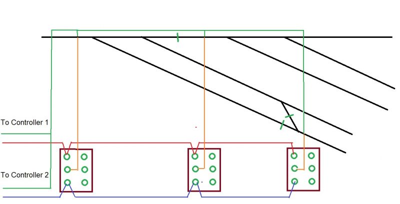
Taking Ron's Diagram, I have added switches to make it dual control. With Point Switching ysliou should be OK but if you are using your slide switches to back up your point blades, you will need extra insulators but let us know
Mark 1 of your diagram is attached for common rail
Regards from Oz and Happy New Year!
Trevor
 Last edit: by xdford
Posted
Full Member
Please excuse tardy reply, thank you for the diagram, Trevor.
I currently have everything working as per Sols diagram above, feeds at the left and at RR and have put conducting connectors between T2 and T3, nothing went 'Bang'!
As it is, I have to have T1 switched to either the platform line or the run-round line to power them, but that's no bad thing.
Having a break from 'lectrics, doing a bit of my favourite, card and paper…
Douglas
'You may share the labours of the great, but you will not share the spoil…' Aesop's Fables
"Beer is proof that God loves us and wants us to be happy" - Benjamin Franklin
In the land of the slap-dash and implausible, mediocrity is king
"Beer is proof that God loves us and wants us to be happy" - Benjamin Franklin
In the land of the slap-dash and implausible, mediocrity is king
1 guest and 0 members have just viewed this.