hand held controller
Posted
#160683
(In Topic #9105)
Full Member
why wont this work
Ive searched and searched and have not seen this question or and answer. I want a hand held controller dc not dcc. I have a pulse throttle. but I don't like how it makes the motor hum and buzz I was told this is just the nature of the beast.My question why cant I just connect a potentiometer to my controller. Crank it up and use the pot to control what goes to the track seems to be the same as what the regular controller/power pack is doing.
Thanks
Dick

Posted
Guest user
I may be wrong but I think the arm on the potentiometer only deflects as a result of the voltage passing through it. It doesn't actually have the ability to " control" the voltage as such. It's deflection only measures.
A controller on the other hand is not much more than a variable resistor. As the knob is turned ( increasing or decreasing the resistance value ) the " resistance " to holding back or allowing power to flow is increased or decreased allowing more or less power to be delivered to the track.
I've maybe not the best at explaining these things but I'm sure that someone else will be able to elaborate a bit better.
I hope I've been of some use
Cheers
Toto
Posted
Full Member
Posted
Guest user
I'll crawl back in my hole………..apologies
Toto
Posted

Site staff
Perhaps adding a non-electrolytic capacitor across the controller output would tend to smooth it better.
Just found this for reading
http://www.instructables.com/id/Simple-controllers-for-DC-motors-inc-PWM-inertia/
With DC controllers, all knobs are potentiometers but with transistorised units, the pot does not have to be a heavy duty as it drives the transistors, not like the older wire wound units of Hornby/Tri-ang/ H&M. A variable resistor/potentiometer by its nature drops voltage & the amount it drops depends on the current drawn by the motor so two different motors may have a different speed at the same setting of the knob.
Ron
NCE DCC ; 00 scale UK outline.
NCE DCC ; 00 scale UK outline.
Posted
Full Member
Posted
Site staff
The Model Shop for Big Imaginations | Gaugemaster
select Gaugemaster Controls
or
Gaugemaster Multi scale Analogue controllers Products from Hattons Model Railways
or
http://www.morleycontrollers.com/Details.asp?ProductID=62
Ron
NCE DCC ; 00 scale UK outline.
NCE DCC ; 00 scale UK outline.
Posted
Full Member
Dick
Posted
Full Member
I can recommend Morley Controllers. No connection with the company, etc. Each controller comes with TWO handheld controllers and a built-in CDU for changing turnouts (is that switches in the USA?) The prices are very competitive compared to other makes.
Terry
Posted
Site staff
 Last edit: by Sol
Ron
NCE DCC ; 00 scale UK outline.
NCE DCC ; 00 scale UK outline.
Posted
Full Member
Edited to say, sorry I didn't realise how old the topic was. :roll:
Last edit: by peterm
Cheers Pete.
Posted
Full Member
Dick
Posted
Site staff
http://jjhobbiesonline.com/store/catalog/product_info.php?cPath=25_46&products_id=77
Ron
NCE DCC ; 00 scale UK outline.
NCE DCC ; 00 scale UK outline.
Posted
Full Member
Cheers
Trevor
Posted
Full Member
Posted
Full Member
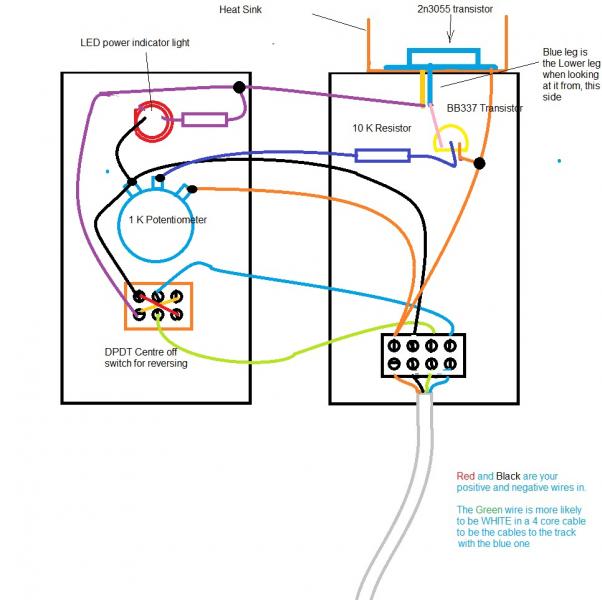
This was a while in coming … It is only a first stage as I intend to do a photo essay on making a throttle but it will get the ball rolling
This is shown on the inside of what we call a jiffy box and from the connection points of the items you put in. In some cases the relative are a bit exaggerated and certainly the colours in the wires are. We will be making a few of these for the club I am in so I hope to photograph as I do one or two,
Let me know what you think,
Regards from Oz
Trevor
Last edit: by xdford
Posted
Full Member
Dick
Posted

Full Member
Shaun.
Posted
Site staff
Red and Black are your positive & negatives wires in
so that means it is a DC input.
Ron
NCE DCC ; 00 scale UK outline.
NCE DCC ; 00 scale UK outline.
Posted
Full Member
The ones that we build are the same as Trevors, but as we are using 15 volt transformers, we build in a four diode circuit to give us DC.
Thought it was worth mentioning.
Shaun.
1 guest and 0 members have just viewed this.