Electrics - D C C
Posted
#198180
(In Topic #10999)

Full Member
Avoiding Short Circuits
Hi All I have just purchased a Multimeter, but, how do I use it to check Polarity, Short Circuits Etc. It is fine having the tools, but useless unless you know what to do with them.:oops: all the best Kevin
Staying on the thread Kevin.

Posted

Site staff
How to use a Multimeter,
you get many results such as this
How to Use a Multimeter - SparkFun Learn
Ron
NCE DCC ; 00 scale UK outline.
NCE DCC ; 00 scale UK outline.
Posted
Full Member
Staying on the thread Kevin.
Posted

Full Member
'Petermac
Posted
Full Member
Regards from Oz
Trevor
Posted
Full Member
That is the basics and should get you started for now until you can provide the picture requested to help you.
Posted

Full Member
No. If you want to accurately measure DCC you need the innards to recognize an AC square wave as opposed to a sine wave. There are special meters for this but most multimeters will give a reasonably accurate reading. Mine does.
Check the following, which gives a very clear and concise explanation of what DC and DCC control are all about:
https://sites.google.com/site/markgurries/home/technical-discussions/dc-versus-dcc-bacground

The square waveform of DCC is so the information bits can be transmitted (0, 1, it's binary code). It's why a voltage drop in very large runs is an issue, the signal becomes degraded and unreadable. For most of us with a 10-30 feet run it's not an issue. Note the difference in frequency - 50-60 Hz is household AC, 7100 Hz is DCC frequency (over 100 fold more so that the signals can be usefully transmitted).
I use a DC powerpack for checking for shorts, dead sections, voltage drops, etc. A torch battery and lamp serves just as well for this. If you want to measure voltage drop over a track run then DC current or regular 12v AC current is fine and it's accurate. I set my meter to 20v DC (solid line above a dotted line). For AC (~) I have 2 settings, 500 and 200v. It's a digital meter, accurate enough over the 0-200v range (±5% from memory). Shorts or resistance, they don't care whether it's AC, DCC or DC. If it's a short with DCC it switches off anyway. One way to test the system is to simply place a coin on the rails. The red light comes on and everything stops. Take it off and everything runs.
Looking at the above shows why DCC is bad news for a DC motor. Being hit with a change in current direction 7000 times a second is not conducive to longevity. Things soon start to warm up, there is a noticeable and ominous hum, and smoke starts to rise from the motor as the insulation on the windings melts
The time to worry about all of this is when you have your puzzle built and running. It's always worthwhile double checking that the dropper leads respect polarity (positive/negative). This applies to DC and DCC. Most of us have crossed our wires at some point in our modeling efforts.:oops: That's why it's useful to have color coded wires and a left/right side (or Up and Down). Odd bits of different colored wires under the board are not to be recommended. I stick with black and red.
When I first started 12 years ago (I came to the hobby late in my mid-50's) I laid a piece of track with one turnout to a siding (a Peco insulfrog which is DCC-friendly as is, not an electrofrog) until I got the hang of it. No droppers, electrical connection through the fish-plates, crocodile clips at the end of the track to the DC power-pack. Learned a lot in a few nights. I then moved on to the layout.
Nigel
©Nigel C. Phillips
Posted
Full Member
Staying on the thread Kevin.
Posted
Full Member
'Petermac
Posted
Full Member
Staying on the thread Kevin.
Posted
Full Member
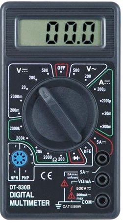
This is a description of the generic operation of a digital multimeter so there will be some real basics here and I hope it applies to you.
The picture shows a typical digital meter but not necessarily the one that Kevin has.
For the purpose of the exercise, I will refer to approximate analogue clock positions for the position of the selection switch and the markings which are around it.
You will have been supplied with two leads, one black and one red. Place the black one in the COM- socket on the bottom Right Hand Side and the Red one in the VW mA socket, that is the middle one on the right hand side.
The Resistance Scale
The main scale you will use for most purposes is that between 6 and not quite 9 o'clock and is designated by the W or Greek letter “Omega†used as the representation of “Ohms†the unit of electrical resistance.
When you select any of the ranges and hold the two probes together, the scale will read close to “0.0†but more likely will read say “0.4†or “0.5†but very close to zero. This number will more than likely increase slightly as the battery inside gets older/loses its charge etc. A mechanical meter can be aligned to zero but digital meters cannot be… well at least the cheaper generic ones anyway!
If your meter reads “1†in the first part of the read out only , using the mathematical definition of “unityâ€, you need to switch your resistance to a higher scale as it means that the scale is too low. If you want to see how the “1†actually looks, hold your probes apart in mid air so you will learn what to recognise!
VOLTAGE
Between 9 and 12 o'clock there is a scale which is intended for DC voltage signified by Vˉ. The 5 scales reading are on the meter shown, 200mV (milli volts), 2000 mV (or 2 volts), 20 (volts), 200 and 500 volts. On a standard DC layout, expecting 12 volts or less, you would set this to 20 volts.
Between 12 and 2 o'clock there is a scale which is intended for AC voltage signified by V~ . The 2 scales reading are on the meter shown are for 200 and 500 volts AC.
If you were checking for the presence of voltage, you would set the meter at the highest AC voltage. If you have a DC voltage which you try to measure on the AC scale, you may see a higher voltage than you expect but no harm will be done.
TRYING OUT THE VOLTAGE SCALE
To try this out I would suggest using a torch battery, a 9V battery or a 1.5 volt battery.
Set your voltage scale to DC voltage. Any voltage will do. Notice that your meter will only read 4 digits and a decimal point!
If your meter reads “1†in the first part of the read out only , using the mathematical definition of “unityâ€, you need to switch your voltage to a higher scale as it means that the scale is too low.
If your meter reads a minus sign, it means you have the probes touching the wrong side. Simply reverse the probes.
If your meter reads “0†or “0.0†, it means there is no voltage present in that part of the circuit
No harm will be done in any case of a wrong connection.
CHECKING YOUR RAIL CIRCUITS FOR CONTINUITY
The most common tasks most Railway modellers undertake with a meter is checking the continuity of the wiring. Before checking for continuity, make sure that your DCC or DC power supply is disconnected, otherwise your meter may read part of the power supply circuit such as the resistance of a transformer or an LED indicator.
Before checking your circuit make sure that there is no voltage present by checking with the highest AC voltage scale then a DC voltage scale. Place one probe on one rail and the other probe on the other rail. Your meter should read “0.0â€
If there is definitely no voltage present, set your resistance to the lowest scale on your meter.
Again placing one probe on one rail and the other probe on the other rail. Your meter should read “1†. Turn your meter to the highest resistance scale, in the case of the above meter 2000k ohms or 2 million ohms and theoretically it will still read “1â€.
If you are using DCC, place your probes on the same side of the track at different points so if you have a point-to-point you would check the resistance touching the front rail at 2 or more different points and the resistance will read
“0†or the the most 2-3 ohms to signify that there is some resistance. The lower this figure is the better. Do the same for the back rail.
If your layout is a Roundy-Round or the track runs in different directions, envisage a train moving forward and measure the right hand running rail points then the left hand running rail or inner and outer rail at points. If there has been a mistake with the wiring in either situation then you will see a “1†indicating an infinite resistance (meaning a lack of continuity) and contacting the other rail will show a “0.0†or a very low figure of perhaps 1 or 2 ohms maximum.
If any of you reading this are using DC and block switches as I do, place all your blocks to the one cab and do the testing as I outlined it above. The resistance will read through switches and you can check for continuity. Switch all your blocks to the other cab and repeat.
As per all my postings, perhaps a little more information from you and a bit of feedback as to how simple or complex this was for you would be good for self improvement, but I hope this helps
Regards from Melbourne
Trevor
 Last edit: by xdford
Posted
Full Member
Staying on the thread Kevin.
Posted
Full Member
 )
)
'Petermac
1 guest and 0 members have just viewed this.