Split chassis DCC conversion
Posted
#251074
(In Topic #13794)

Full Member
Wiring a split chassis for DCC
Hi all,We've had some recent commentary about "how difficult is it to convert a split chassis to DCC?" The following should be of use to anybody wanting to convert a split chassis, DC, locomotive to one wired and ready for DCC, Nothing very complicated, but I will highlight some of the issues as I go along. This method works for steam or diesel split chassis. I actually like split chassis locomotives, lots of weight, excellent electrical contacts through split axles, and no wheel wipers. Downside is often a lack of space for decoders, speakers, and stay alives, but it's amazing what the "big file" or the Dremel can achieve. On a steam locomotive it's always worthwhile making sure the CoG is over the center of the chassis. I have a model awaiting conversion to DCC, so here it is.
Part 1 is wiring the motor for DCC, part 2 is wiring the chassis for the DC supply.
Part 1. The conversion subject is a Bachmann Spectrum 2-6-0 mogul, sans front bogie as it will eventually end up as an 0-6-0. split chassis. Bachmann Branchline split chassis locomotives in the UK were/are made by the same company, and fortunately some of the small but crucial parts are common to both.
First off is to get the body shell off the chassis. Split chassis designs often have a combination of screws and lips, usually a screw underneath the cab, and a lip at the front. Consult a reference diagram for your model. Once off and the base plate and wheel set removed, check for split axles. If you see hairline cracks in the central plastic part, and/or the wheels are loose where the stub axles go into the central carrier, think hard before going any further. Older models often have a different axle design to their more modern equivalents, I have been caught out on 5 models (3 Manors, a K3, as well as a Mainline pannier, all made by Bachmann/Kador). Unless you are sure you can get replacements (or a cheap, newer wheel set) I strongly recommend stopping here. That cherished model is just about to become a money pit and an endless source of frustration.
All being good on the axle front (no cracks or splits, wheels tight on the plastic carriers on this one), the next step is to split the chassis. Most models are held together with 3 plastic nuts, plastic spacer washers that go between the chassis halves, and metal screws, along with a couple of white plastic spacer inserts at the bottom where the base plate screws go. Check the plastic bolts for wear and fatigue. If questionable or if the threads are stripped Bachmann USA has spares, as well as washers and screws. Bachmann in the UK is somewhat iffy about these spares.
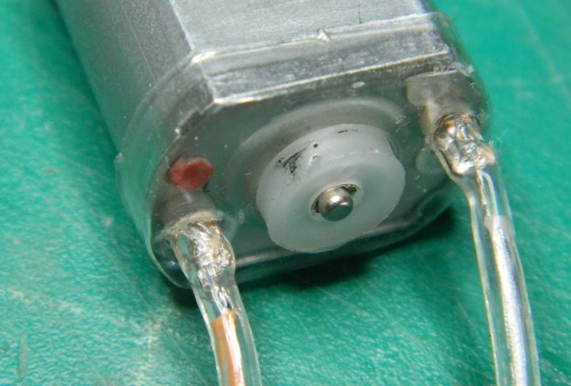
Remove the motor, remove the contact springs from the chassis sides and bin them. Keep the transparent plastic cover that goes over the end of the motor as well as the thrust bearing. UK models will usually have a mess of RF control electronics, not needed if running DCC. I bin the lot. Solder the wires that will come from the decoder to the motor (grey, orange, use heat shrink slid over the wires and contacts to insulate). I never hard-wire decoders, there will be a connector between the motor and decoder. Slide the plastic cover over the wires and onto the end, and refit the end thrust bearing.
Now is the time to clean out the old grease and replace with new. Same goes for the wheel set.
Drop the motor/worm into one chassis half, reassemble the other half, the tricky bit is keeping those white spacers in place. Some white plastic compatible grease works well. Drop the wheel set in, attach the base plate. Job done.
All of this took just under 30 minutes.
Nigel
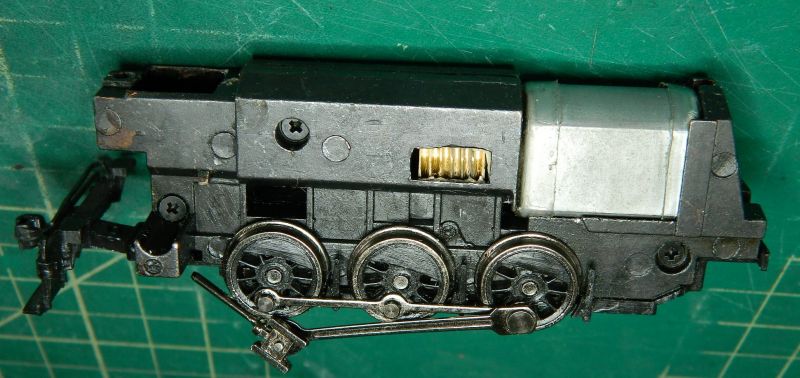
The conversion locomotive, a Bachmann Spectrum Mogul sans cab and front bogie. This had a screw at the back and a lip at the front. Cab is off because this is destined to be an 0-6-0 On30 shunter with a new cab.

The split chassis - exactly what it says.That big hole at the front is for the smoke unit. Just enough space for a sugar cube speaker if desired. The gap between the chassis halves provides some space for wiring.

The 3 screws that hold the two chassis halves together.
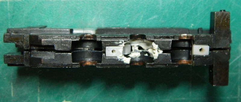
Bottom plate removed, the white spacers also serve as the bottom plate screw holes.
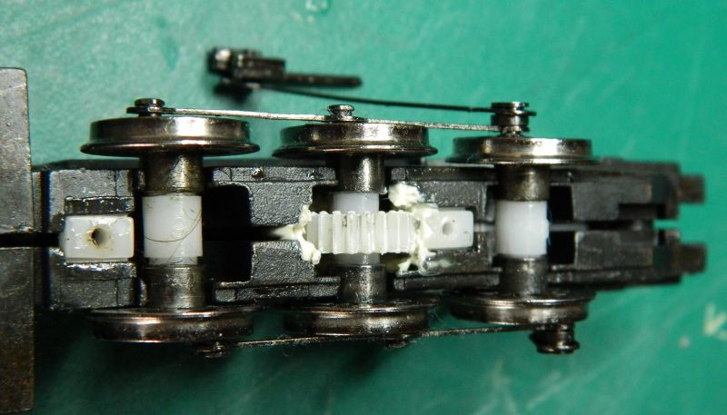
Wheel set removed. Note copper/bronzed bearing surfaces. Some models will have a central spring in a hole in one bearing on one side to provide some equalization.This model didn't.
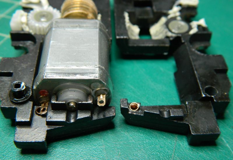
The split chassis split. Note the nut and spacer washer on the bottom half. The worm on these motors is also the flywheel. Some models will have a carrier gear in addition to the drive gear. Good time for a clean and lube.
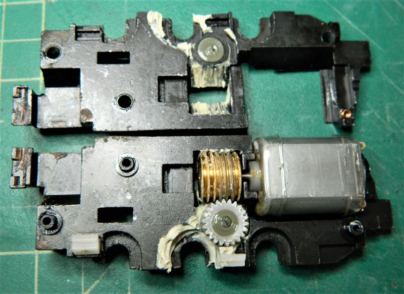
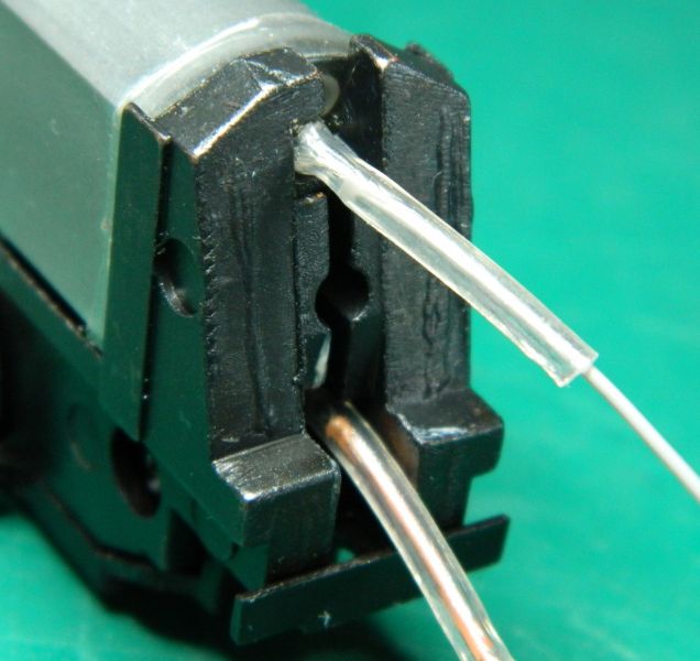
Motor end of the chassis. Spring contacts on each side for the motor terminals. They are not needed, I bin them. Most models don't need it, but some alloy can be removed from the spring area if it's a bit tight for the wire/heat shrink. Note the clear plastic cover over the end of the motor, reuse it.
Motor wired up and with heat shrink. Plastic cover also back in place. On older models the plastic cover is often damaged or very fragile. Kapton tape can also be used if required as a substitute. Do not use electrical tape.
Motor in chassis. That's half the job done!
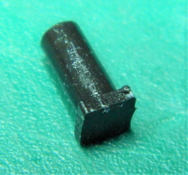
This a spacer nut. In good condition on this model. If the threads inside are stripped or if it is perished get some new ones.
©Nigel C. Phillips

Posted
Full Member
Part 2. Wiring the chassis.
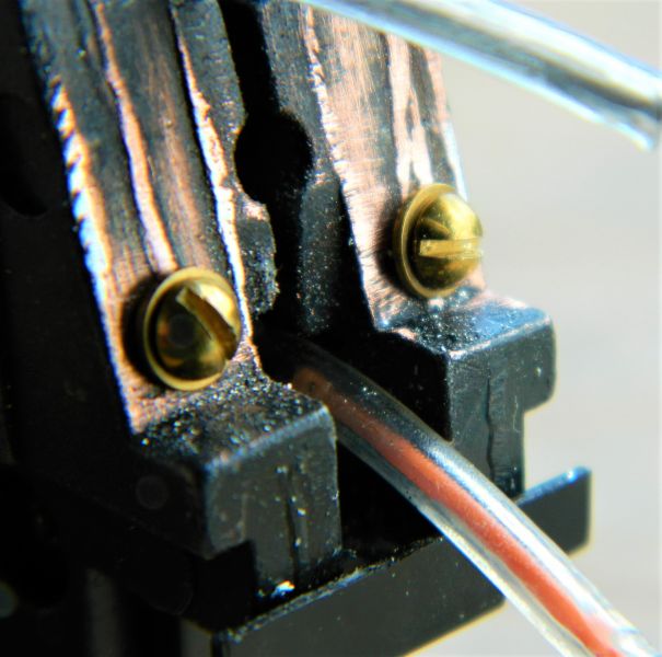
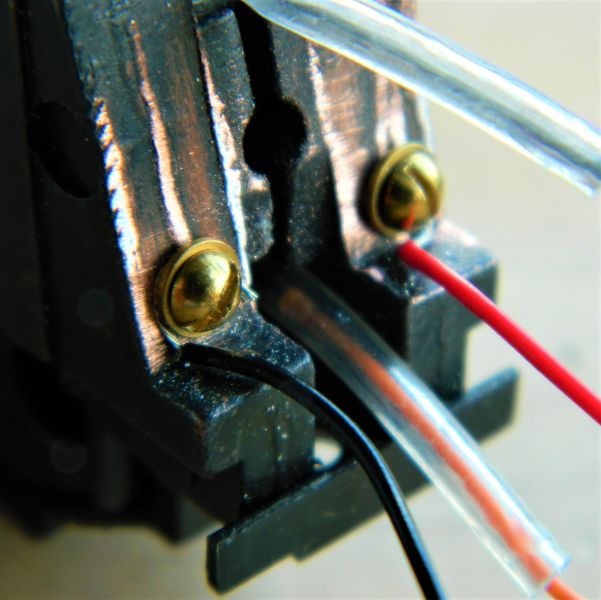
Holes for 2-56 bolts were drilled and tapped in a suitable location following paint removal (kit from Kadee contains the drill bits and tap), 2-56 brass bolts and washers were then inserted. Red/black wires to the decoder were then attached and the bolts tightended. At this point there is usually no need to solder the wires, but if desired they can be soldered to the washer (before or after attachment)..The keen-eyed will note that the chassis is electroplated with a thin layer of copper. The brave-hearted or (foolhardy) may be tempted to solder the wires to the copper layer after gently removing the paint. It can be done (I've done it with a couple of conversions) but that was long ago when I was young and easy and didn't know better. .
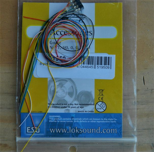
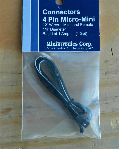
As I mentioned in the previous post, I am not a fan of hard-wiring decoders to a chassis (split or otherwise). Eight, 21 or more recent pin adapters are readily available. For 8-pin decoders and locomotive-located decoders I use a female socket, pre-wired, one example are those supplied by ESU. For tender locations I use mini plugs and sockets pre-wired and wired to the DCC adapter in the tender, one example being those supplied by Miniatronics (common arrangements are 2- or 4-wire cables). These provide a means of easily separating the locomotive from the tender as required and flexible enough to go round curves in the track.
That's it. With today's drilling and tapping less that 1 hour in total to do the conversion.
I have no connection with any of the companies mentioned (Bachmann, ESU, Kadee. Miniatronics) other than as a satisfied customer.
Nigel
Holes drilled, tapped and bolts and washers attached. Note the copper layer under the paint.
Red and black wires attached. Brass washers provide a good surface for soldering.
ESU 8-pin adapter.
Miniatronics 4-wire connector.
©Nigel C. Phillips
1 guest and 0 members have just viewed this.