MERG DCC Kits
Posted
#200316
(In Topic #11100)

Full Member
Matt sugested I turn some of my recent posts on MERG DCC Kit constructions in to a set of tutorials, being easier to find here than in the middle of my layout thread.
Taken from the MERG site
MERG (Model Electronic Railway Group) is an international, UK based group promoting interest in the application of electronics & computers to all aspects of railway modelling.
Founded in 1967, the Group’s aim is to actively promote and advance the use of electronic and computer technology for model railway operation, which is ideally suited to take advantage of these technologies, and the application of electronics and computers can be used to good effect to add enhanced features and realism to model railway operation.
MERG sell to members a range of kits, suitable for DC & DCC, ranging from simple Pocket Money Projects casting a couple of quid designed to be an intrdution to electronic kit construction, to DCC Comand Stations, Boosters and Hand controllers, some using surface mount technology.
To Make things easier to find here is a rough index
Kit 56 DTC8 - 8ch DCC only Current Transformer Block Detector Post 1
PMP7 DCC Train Detector Post 5
Kit 53 DCC Steady State Accessory Decoder Post 12
Kit 75 Servo4 - F Quad servo driver Post 13
So the first kit tutorial will be the DTC8 - Kit 56
8ch DCC only Current Transformer Block Detector, DTC-8 Part Number: 56
How they ever manged to get all the bits into the I'll never know….
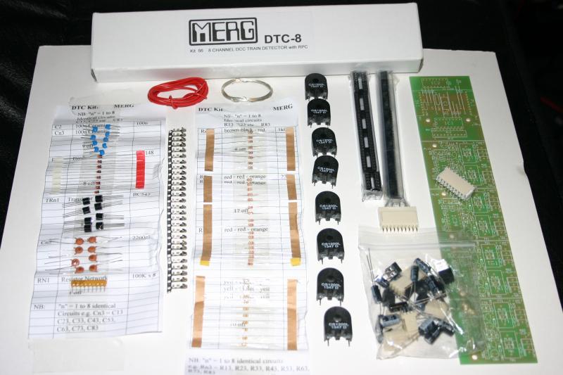
This kit will produce 8 current detection sensors. The board also has a Remote Panel Control (RPC) Interface, for this tutorial I will not be using this functionality. The board is designed so that the 8 detectors can be in one unit, or can be split into pairs, this is how I will be building this kit.
The instructions are comprehensive and should be read before starting - I know its not manly, but niether is the sight of a man crying, melting the ends of his fingers trying to remove the bits as he forgot to install the smallest part.
Tip Number 1
LEDs, Electrolytic & Tantalum Capacitors - the longest leg is the +ve
First step (for me) was to split the PCB into 4 dual detector board, and discard the RPC section (left hand section)
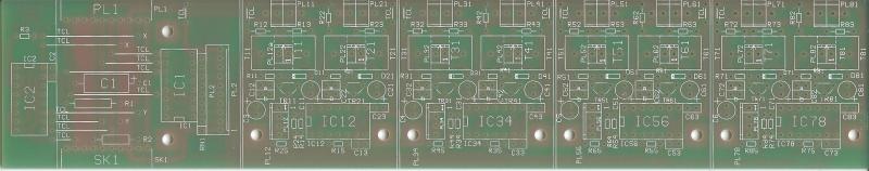
All the MERG kits follow a similar format start with the smallest components and work up, this allows you to keep the parts flat against PCB when soldering
So wire links, followed by resistors, diodes and small capcitors
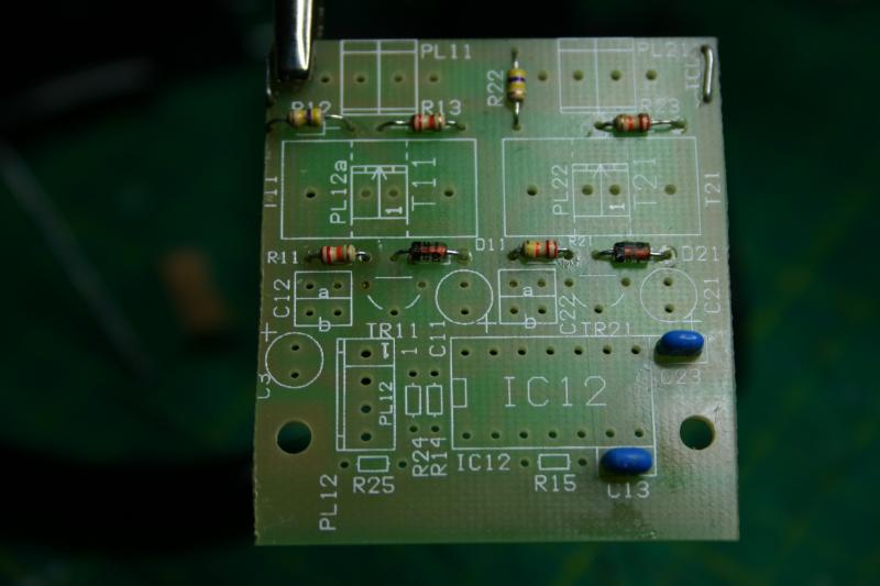
Next the 14 way DIL socket, transistors, electrolytic capacitors and molex connector
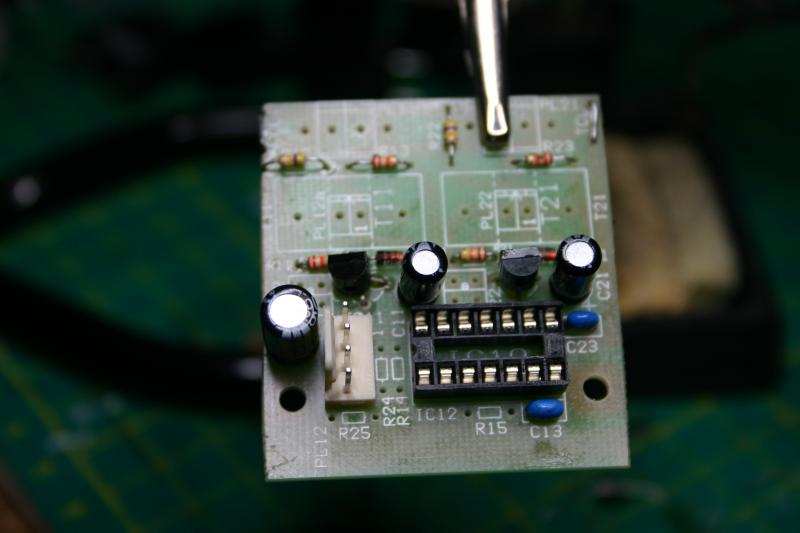
The fun part the two detector coils, then loop the red track coil wire through the dector coil. Finally fitting the terminal blocks.

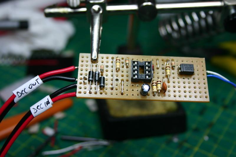
Finally, you get this :-
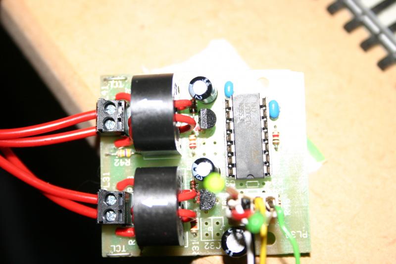
Picture above shows a jury rigged detector socket
The 4 pin Molex socket is as follows Left to right Pin 1 (white) +5V, Pin 2 (black) 0V, Pin 3 (yellow) Output 1, Pin 4 (green) Output 2. An led is connected between Pin 1 & 3, another between Pin 1 & 4, to give an indication of an output.
When installed the leds will not be included.
A very rough video can be seen here
https://www.youtube.com/watch?v=LgHb-JlK8lQ
Paul
 Last edit: by paul_l

Posted

Full Member

It looks very neat but I'd like to see the other side - the bit with the solder blobs on it ………….:roll::roll: If I tried it, I'd have everything either shorting out or dry jointed. :cheers
'Petermac
Posted
Full Member
Re-posted the link, seems to work now :roll:
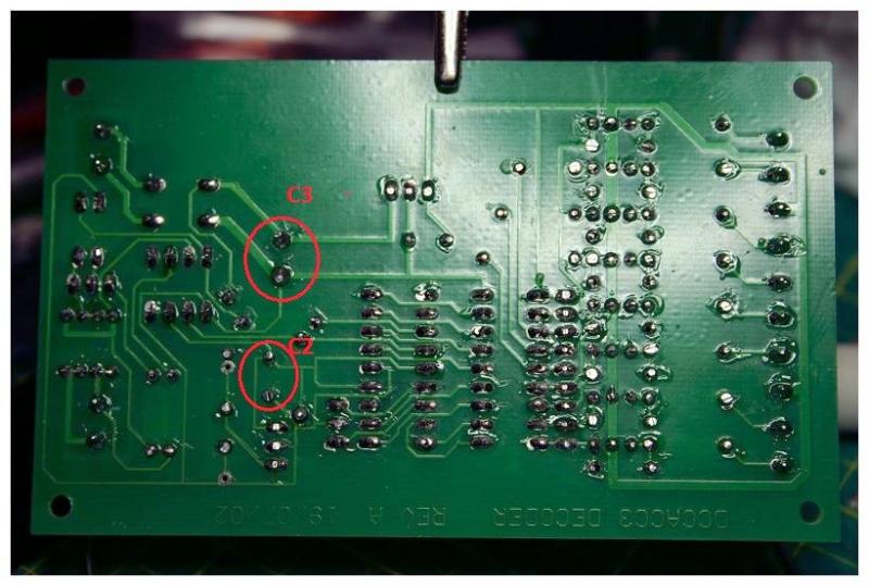
as requested the other side
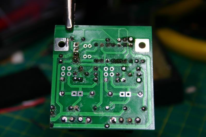
Still have to clean the flux off
The square solder pads un-used in the centre allow a terminal block (not supplied) to be used to use the detector coils off board
I find a magnifying glass very handy to check the joints, and recently using that to check the joints as I make them, less than two weeks between the above photo and the last one I made the CANACC8 below, this one still needs cleaning as well.

A fine tipped soldering iron helps.
Paul
Last edit: by paul_l
Posted

Inactive Member
It's very interesting.
I tried to join MERG some time ago, but their site kept blocking my credit card.
I sent them an email, but got no response.
I wish I'd persevered.
Keep 'em coming. :thumbs
Max
Port Elderley
Port Elderley
Posted
Full Member
MERG PMP7 DCC Train Detector
This is part of the MERG Pocket Money Project range of kits, designed to help users gain confidence in building kits, but also to teach new skills and be useful.
The circuit works by using a dual comparator chip to compare the current flow accross a pair of diodes, if their is a loco on the track section, there will a current flow, this will cause a difference across the diodes, and the comparator detects this, and turns on the the optoisolator output. Theres a bit more to it than that, however the circuit will use a little current from the track bus and my drop the voltage.
As this is a stripboard based project, you have mark out the breaks in the tracks
and then cut the tracks, you can buy a tool for this (approx £12 from Maplins, £6 from the bay), or use a 3mm wood drill (my method), or if you must use a knife
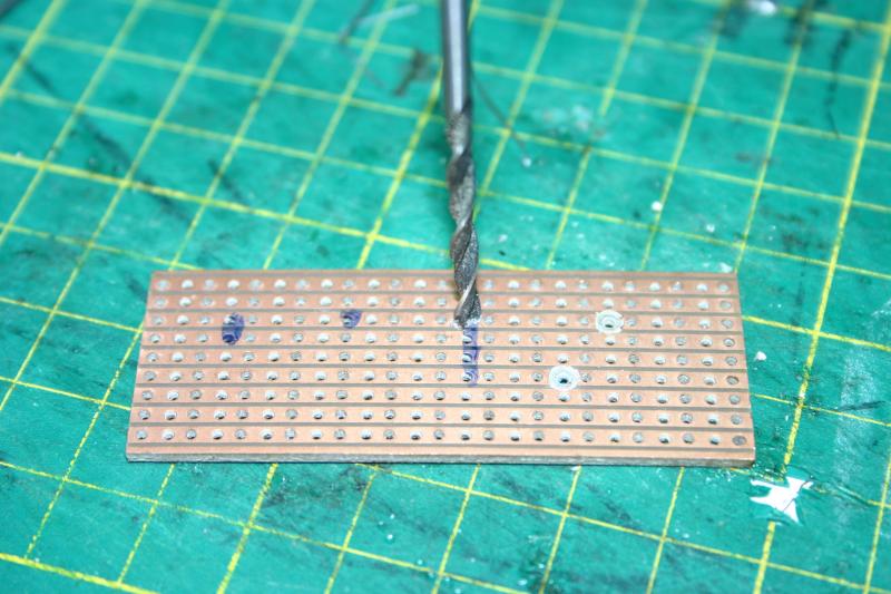
Once all the breaks are completed, clean the board, and check that there are no stray connections, I use a multimeter with a continuity checker, but Max's Jesus box would work just fine.
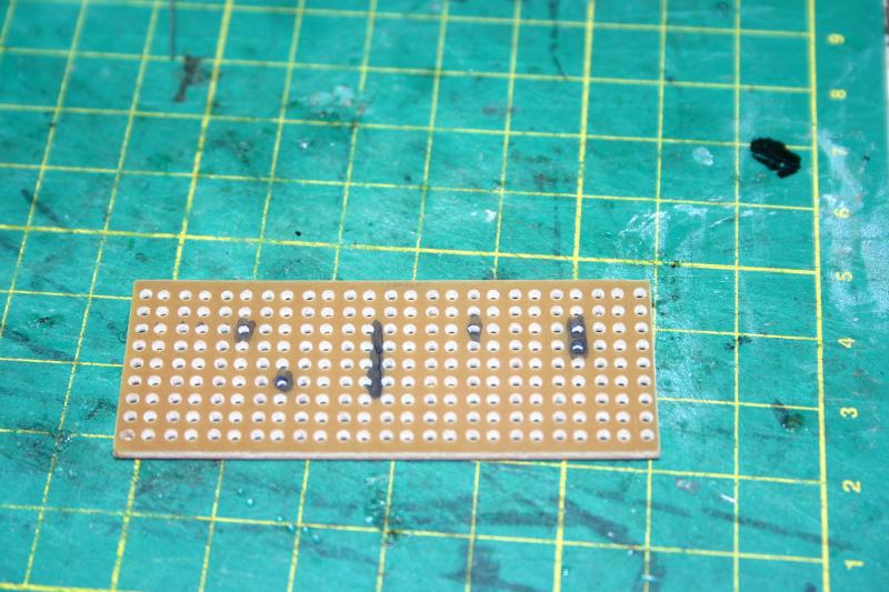
As with the other builds start with the thinest components first, this allows you to hold them flat agaisnt the board with minimal pressure.
So wire links, 1K resistors, 1N4148 Diode, 100K resistors, remaining diodes, TLP521 Opto isolator, ceramic capacitor, DIL socket and the electrolytic capacitor.
I did make 1 modification, as the black wire is common to the input and output & the 3rd track from the bottom has no connections, I added a wire link between the 3rd row and 4th row to make it easier to connect the DCC wires as can be seen just to the left of the diodes.
I haven't added the LM393 dual comparitor chip, until the board is cleaned & tested.
Cost £1.50, plus a hours work. To be honest this took longer than normal as I had to keep counting the holes to get the correct position of each component, but thats normal for this type of circuit.
Paul
Posted
Inactive Member
Thanks for those pics and descriptions, it's all interesting stuff. I hope you don't mind if I ask a few questions.
The PMP kits are new since I left MERG and the detector looks novel. Do they claim some special advantage over the usual two diodes in series setup? I can see from the pics that you only get one diode voltage drop, but I'm not sure that it gives any advantage. It looks like an interesting circuit though, and it would help my understanding of how those comparators can be used.
Is it easier to connect to an external circuit than the inductive detector? It looks like a simple on/off output but I don't know what the other one uses.
I think I will spend a bit of time tomorrow trying to work out the schematic from those pics to see if I can understand what's going on.
The BC3 controllers use the quad version, LM324, in some ingenious ways, and I have seen a MERG circuit for a detector using LDRs that also used a 324. It seems to be a favourite of JJ Matthews - Did he have a hand in this one?
Regards,
Brian
ECoS, Laptop, TrainController Gold v8
Brian
ECoS, Laptop, TrainController Gold v8
Posted
Full Member
From the instructions
"A stationary loco on that track will draw a tiny current to power its decoder, while a moving loco will draw even greater current. In both cases, the current produces a stream of voltage pulses across the diodes. These pulses are
fed to pin 2 and result in the output pin 1 having a pulsed output. The pulses are routed via the 1N4148 diode and increase the charge on the 10nF capacitor until it reaches approximately half the supply voltage. At this point the second comparator turns on and switches on the opto-isolator."
Also then the block empties (or a bad connection), the output stays on untill the the capacitor discharges helping to debounce the circuit
There some quite neat PMP projects, and nearly all under £2
Paul
Posted

Full Member
Some great "How to's"
Much better to have them in their own thread.
Joined MERG

Not sure if I am more confussed now, though.
A question;
Can I use my DCE PowerPro and a Cbus?
The PowerPro for the trains and the Cbus for everything else?
Cheers,
Ian :mrgreen:
Time flies by when I'm the driver of a train
And I ride on the footplate there and back again.
Cooper St.
And I ride on the footplate there and back again.
Cooper St.
Posted
Full Member
Welcome to the club

To use cbus with the NCE PowerPro you will need the CANUSB Cbus/PC interface and a connection to the PC from the PowerPro. Plus software to connect the two. I use JMRI, Toto uses (or will use) RR&Co.
I'm away in the big smoke on a training course next week, hopefully when I return I will try and cover setting up the powercab /jmri / canbus.
Paul
Posted
Full Member
That is what I had sort of got in my head, its the finer points, lol
I have ordered my first pocket money kits to try my soldering;
Code Kit name Qty 490 LCB Experimenter's Kit 1 814 PMP14 - Decoder Test Rig 1 461 Gas Lamp Twinkler SMD 1
So I have downloaded JMRI, again lots of reading.
At least I am in your camp with setup and control, when I get around too it
Once again great work :pathead
ATB,
Ian :mrgreen:
Time flies by when I'm the driver of a train
And I ride on the footplate there and back again.
Cooper St.
And I ride on the footplate there and back again.
Cooper St.
Posted
Inactive Member
It looks as if the leftmost 1K is connected to the diode pair at one end and pin 2 at the other, as described in your instructions. It looks also as if the 100K 3 holes to the right is also connected to pin 2, and I cannot see anything connected to pin 3.
There must be something I cannot make out in the photo. I am also having trouble understanding how connecting pin 2 (negative input) to DCC Out will hold the output of op-amp1 low in the absence of current flow, but that's my problem.
Edit: Thanks for the PM, I posted before seeing it. That should solve my problems.
Last edit: by Brian R
Regards,
Brian
ECoS, Laptop, TrainController Gold v8
Brian
ECoS, Laptop, TrainController Gold v8
Posted
Full Member
Just like with Toto, you get homework.
One of the decisions you will need to make is how do you intend to operate the layout.
1. Just drive loco's etc from the hand set - operate points signals etc via the PC
2. Control loco's & points etc from the hand set .
If the answer is 1 then accessory decoders can be either on the track bus or canbus.
If the answer is 2, then the accessory decoders need to be on the trackbus, not the canbus. This is because the NCE handset does not have access to the canbus.
Track bus compatable MERG decoders are kit 52 - Pulsed outputs for solenoid point motors, and kit 53 steady state outputs for cobalts, tortoise point motors, or relays. The output of kit 53 can be increased with the addition of kit 55 to allow the decoder to control higher current devices like the fulgurex and lamoco point motors.
I have 2 x kit 52's on my layout, but didn't take any photos of them during construction - they were my first MERG kits.
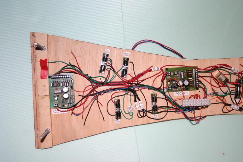
Each kit 52 can control 4 solenoid point motors, the above photo shows seep point motors, each kit having its own integral capacitor discharge unit.
I have however just finished building a kit 53 steady state output decoder.
The decoder can be either used as either 4 way Bideretional decoder, a 1 x 8 output decoder, or a 2 x 4 output decoder (provides Lenz compatability).
All these are set by adjusting CVs.
The DCC Decoder kits are NMRA DCC compliant and are connected to the track bus or accessory bus to obtain the DCC signals. They are powered via an external power source.

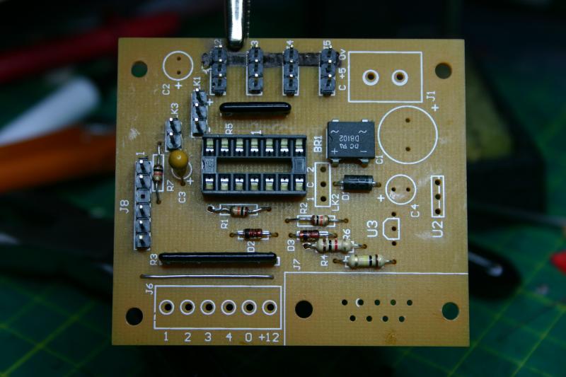
The decoder can be built as - install everything (as per this tutorial) or can be customised on the out put stages to suit individual applications. I intend this decoder to drive servo control units. So carefull reading of the instructions are required to determin if the output resistors, transistors or diodes are to be fitted or replaced with wire links.

The decoder uses an independant 15 - 16V ac supply, into J1.
The DCC track feed is connected to J2.
The track voltage is opto isolated from the decoder via U1, and an optoislated ACk signal is sent back to the track via U4 and R6, enough for the command station to detect the program acknowledge .
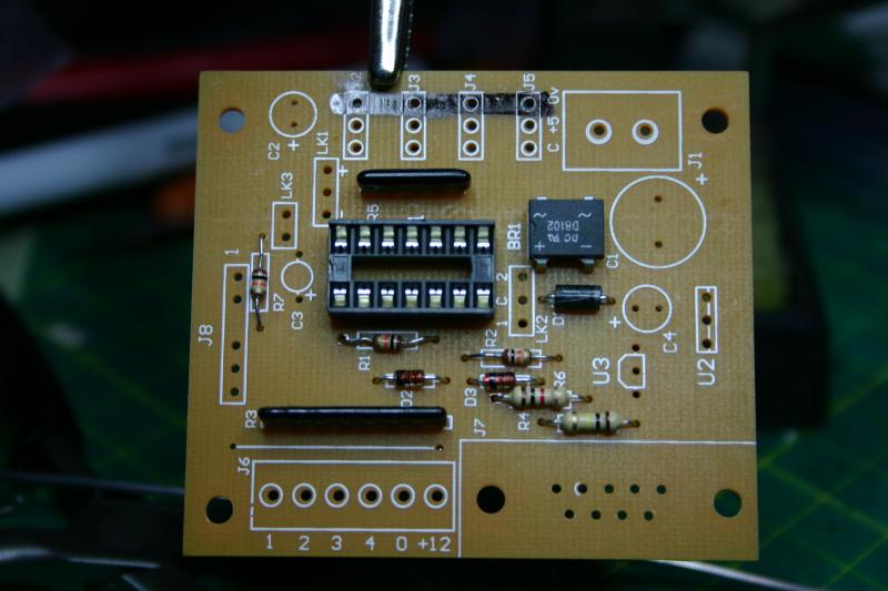
As with all merg kits I've built so far, start with the wire links, resitors, diodes, then the bridge rectifier.

Next up the ICs U1 & U4, the sockets for U3 & U5, and the resistor network
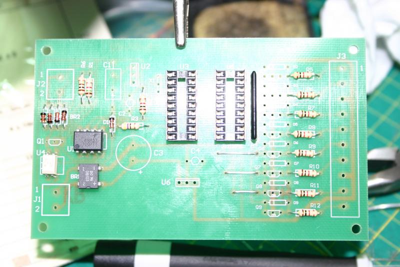
Capacitors C2 & C4, then the terminal blocks. These are supplied in to terminal pairs that link together to make the larger termional strips.
The remaining componemts are fitted as required.

The unit is ready for testing before ICs U3 & U5 are inserted.
A 15 - 16V ac supply is connected to J1, note the voltage, if the voltage is significantly pulled down, this would indicate that excess current is being drawn and something is going to get hot or worse. Disconnect and check fior dors and correct orientation of diodes and capacitors.
If all is well the voltage across C3 should be 15 to 20V DC. Care should be tacken as C3 can hold a fair jolt.
If good then check the voltage across C2 this must be close to 5V
On the upper side put the 0v probe into pin 5 of socket U3 then check U3 pin 14 is +5V, the same voltage should also be on pin 4 - take care not to short the probes.
If all is ok power down, let the caps discharge, then insert the IC's.
The decoder is now ready for programming.
Paul
Posted
Full Member
This kit is not a DCC kit, and operates by a change on one of its inputs, this can be from a switch, relay or DCC accessory decoder output for example Kit 53 DCC steady state output, or CANACE8C output.
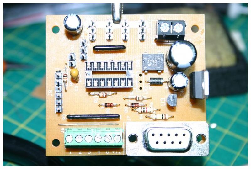
The module uses a 9V ac or 12V dc power supply, and is controlled via a PIC microcontroller. The PIC is programmed via the ServSet2 standalone programmer (kit 76a) or a PC through the serial interface. Settings for start and end of throw and speed are saved in the PICs memory, so unless the servo is changed or the device gets fried then its a set and forget device.
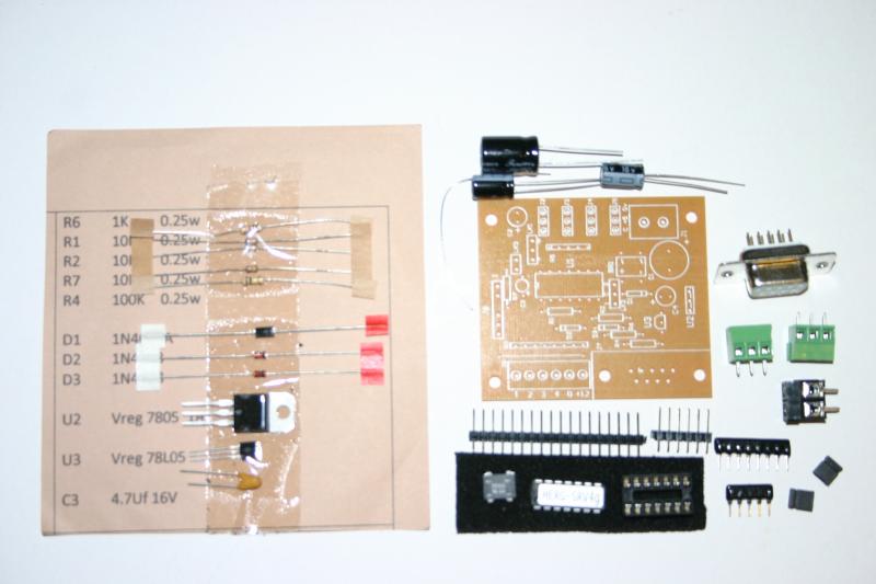
Following the normal practice of fitting the smallest components first, resistors with a warning in the instructions to be carefull the resistor values are 1K, 10K & 100K the only difference being the colour of the 3rd band
1k Brown-Black-Red
10K Brown-Black-Orange
100K Brown-Black-Yellow
Then the diodes and 14 pin DIL socket

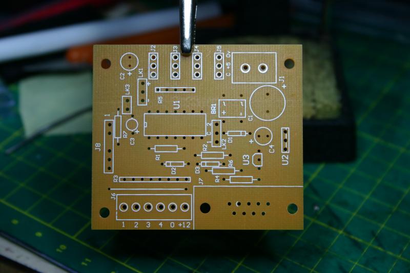
Next the Resistor networks (resnets) and bridge rectifier. The instructions recommend painting a line on the outer row of pins on J2 to J5, to make it easier to get the servo polarity correct.
The supplied piece of PCB header strip is cut into 1 x 2 pin header for link LK3, and 5 x 3 pin headers for J2 to J5 and link LK1. Then soldered in place. I tend to tag one pin roughly in place, then align it vertically and ensure its flush with the surface, take care these get hot quick, especially when your fingers pushing down on the pin.
J8 is optional, and is designed for In-Circuit Serial Programming of the PIC, i'll probably never use it but hey….. But it did mean I had to fit the wire link between J6 and R3.
Now the Tantalum Capacitor C3 is fitted, remembering the longer lead for Tantalum and electrolytic capacitors is the positive. 5v regulator U3 is fitted making sure the curve of the body aligns with the curve on the PCB.
Terminal blocks, 2 way 5mm J1 (black) and assemble the 6 way from the two 3way 3.5mm terminal blocks.
C2 & C4 electrolytic caps
Then the 9 pin D connector, fixing screws are optionall, and the PCB does have holes if required.
Lastly the large 1000uF cap C1 and the TO220 7805 voltage regulator U2 are fitted.
The next part of this how to will cover the testing and setup, but I'm being sent on a training course for a week, so it will have to wait.
Paul
Posted
Full Member
Hi Ian
Just like with Toto, you get homework.
One of the decisions you will need to make is how do you intend to operate the layout.
1. Just drive loco's etc from the hand set - operate points signals etc via the PC
2. Control loco's & points etc from the hand set .
If the answer is 1 then accessory decoders can be either on the track bus or canbus.
If the answer is 2, then the accessory decoders need to be on the trackbus, not the canbus. This is because the NCE handset does not have access to the canbus.
Track bus compatable MERG decoders are kit 52 - Pulsed outputs for solenoid point motors, and kit 53 steady state outputs for cobalts, tortoise point motors, or relays. The output of kit 53 can be increased with the addition of kit 55 to allow the decoder to control higher current devices like the fulgurex and lamoco point motors.
Hi Paul,
My original thought is to control everything from the handset, BUT, I am thinking now that PC control via JMRI for all accessories and the handset for the trains.
ATB,
Ian :mrgreen:
Time flies by when I'm the driver of a train
And I ride on the footplate there and back again.
Cooper St.
And I ride on the footplate there and back again.
Cooper St.
Posted
Full Member
Re-point operation
I use the MERG DCC pulsed output accy decoders, I didn't know about JMRI at the time. So following the recent discussions on Toto's thread I've asked myself, would I use these or the steady state decoders in the future or go for the Cbus modules ?.
The answer is i'm not sure :roll:.
The ability to change points without having to have a computer attached / running just using the handset is a good one, but I must admit I only have 4 points with 6 motors (1 x 3way & 1 x double slip) so its easy to remember which point is which, and I still tend to use JMRI's route tables.
Ths cbus modules allow a degree of programming where the output modules will react to predifined inputs, as well as the PC, but cant be controlled from the handset.
The beauty of the MERG Cbus using the industry standard CanBus, is the interface chips are readily available - even from the MERG kit locker (MCP2551 CAN Transceiver Part Number: 755 - 72p each), so my next MERG order will include a few of these to allow me to try and interface them with an arduino, I already have the bits to do that for the track bus, more to follow.
The last MERG magazine contained an article on interfacing the arduino to the track bus, some reading for the train journey……
Paul
Last edit: by paul_l
Posted

Full Member
.The customer asked "had I not heard of M E R G?" to which I replied No, and he told me about Signal/Point control, and the ability to stop a train at a Red signal, and when the signal clears the train proceeds, to which I replied, but I am using DCC and with DCC:???: the train might go in the wrong direction or start off too fast. Again I stood corrected:oops:, the customer said MERG can do all that. Well Paul after all that, I have now heard of M E R G, so for a" Non Geek" like me is it worth joining?? and has M E R G got the capabilities to supply "easy to assemble kit to do the job" and end my SPAD fear once and for all . ATB Kevin
Staying on the thread Kevin.
Posted
Full Member
The dark side is spreading.
Take a look at post 5 pocket money kit dcc occupancy detector and post 13 servo 4 kit.
These two kits show the two extremes the pocket money kits are really basic, but are a cheap useful way to practice soldering.The servo 4 kit (and others) show the level of professionalism of the kits.The instructions are comprehensive and include testing and fault finding tips.Aĺl parts are clearly identified.The posts above give an idea of the level of complexity, but if you read the posts if they appear straightforward then you should be ok.
As for is it worth joining, my first order was for 2 accy decoders with capacitor discharge units builtin approx £12 each plus membership £15, total £39, a single accy decoder is over £40, so if your prepared to build em, there is a considerable saving to be had. In addition many offer additional features over proprietary alternatives.
Paul
Posted
Guest user
Posted
Full Member
. And I would like to be able to stop trains at "Danger/Stop Signals" and start them when the signal changes to clear. If M E R G kits can do this, just like the shop customer claimed?? If the Pocket Money Kits(it depends on how big your pockets are:cool:) work, and they are less than the price of a Loco:oops: I would wish to "proceed at caution". ATB Kevin
Staying on the thread Kevin.
Posted
Full Member
Paul
1 guest and 0 members have just viewed this.