Kevin's Inglenook Junction
Posted

Full Member
Two Planks Become One
Hi Ed. I followed your example, whether it is the battery or not? at first it was on zero, then it was jumping around just like you said. But now the display is fading, perhaps, shortly I had better purchase a new battery and from a more reliable source. Best wishes Kevin
Staying on the thread Kevin.

Posted

Site staff
Once you've tested the switches when you've got a new battery, I'll post on testing the points.
Ed
Posted
Site staff
To test the points.

With the point set in the straight ahead direction as shown, and the multimeter set to 2000 ohms resistance as before.
With the multimeter probes touching A and B you should get a reading.
With the multimeter probes touching B and C you should get a 1
With the multimeter probes touching B and D you should get a reading.
With the multimeter probes touching B and E you should get a 1
Then change the point and check again, all the readings should be reversed i.e A and B will get a 1 and B and C will show a reading etc.
Ed
Posted

Full Member
Unless you leave the multimeter on, a fresh battery will last months. Ed's pictures just show what I explained to you some time ago.
I can only see one green wire coming from the slide switches, plus what looks like 4 other wires going in. Labeled 1 and 2 on the baseboard.
You really should get that power/control cable connector repaired or get a new one from the UK supplier, especially if you leave it in such an inaccessible location.
A note of warning for you (and anybody else) about the base NCE Power Cab system. The Power Cab needs to be protected. All it has is an automatic short reset that will burn out from overheating with repeated shorts. Unless you have a circuit breaker installed once you have a short you need to immediately disconnect the Power Cab and start hunting. Only reconnect it when the problem has been resolved. Using the Power Cab to see whether the short was corrected is not the way to go.
Because of the low amperage of the base Power Cab system (1.7-2 amp) you are essentially restricted to the NCE CB6 (6 power districts, 1 amp each district, light bulb technology, or build you own from car interior light bulbs) or a DCC Specialties PSX-1 (1 power district, electronic) that can trip around 1 amp. They are around $40 here. A PSX4 (4 districts) is around $130. The CB6 can power 6 power districts, so you can easily identify and isolate where the short is taking place. It is a sound investment, as NCE will not cover track shorts under their warranty. That's why the multimeter is essential, as is checking every inch/cm of track before powering up again. If you know where the short happened it saves a lot of time.
With 2 separate track systems each split by a module junction and that are not interconnected, but are powered using one Power Cab, they really should be treated as power districts (blocks in DC) and wired accordingly so that the investment in the Power cab DCC system is protected. NCE make all of this abundantly clear in their literature. In your case it would make sense to have 4 districts, 2 on each module.
Good opportunity for you to rewire to best practice with respect to wire gauge and consistent colors (for the bus, droppers and switches), power districts, circuit breaker protection. Otherwise you could well be "faffing" around trying to get things running rather than playing trains, and creating even more multicolored spaghetti. I doubt if I would remember what wire goes where.
My plank which is currently being wired has a CB6 and 3 districts for the DCC side (2 for the DC side if I can juggle the wiring on the CB6) and it's only 5 feet long with a 3 foot fiddle yard. And every inch of track is being checked before any power runs through it. Even then it will only get DC to start with.
Keep us posted.
Nigel
©Nigel C. Phillips
Posted
Full Member
Staying on the thread Kevin.
Posted
Full Member
I don't have the luxury of superior knowledge, I leave that to experts. Electrickery is not my forte, but when NCE recommend something I usually pay attention. It is there for a reason. Best practices are usually common sense. Bus wire needs low resistance, use the appropriate gauge/diameter. Keep stoppers short, they are thinner with more resistance. Color code the wiring and keep it standard. Otherwise you will at some point wire it up incorrectly. Keep the wiring neat and tidy, use those write on labels that electricians use. Draw track plans and wiring plans. Update often. Use the multimeter to test, not the Power Cab. Both the NCE and Digitrax websites have a wealth of information that is tried and tested. Those are the systems I am familiar with. Unlike some ijit on ootoob doing it 'is way!
I have operated with DCC for over 15 years now, I have never bothered with DC, except for that layout in the 1960's. If in doubt get advice and help before, not after.
Nigel
©Nigel C. Phillips
Posted

Site staff
Cheers
Matt
Wasnie me, a big boy did it and ran away
"Why did you volunteer ? I didn't Sir, the other three stepped backwards"
"Why did you volunteer ? I didn't Sir, the other three stepped backwards"
Posted
Full Member
Staying on the thread Kevin.
Posted
Full Member
Staying on the thread Kevin.
Posted

Site staff
Ron
NCE DCC ; 00 scale UK outline.
NCE DCC ; 00 scale UK outline.
Posted
Site staff
And I am glad that we Down Under changed our current from pence, shillings & pounds to Decimal as we did with weights & measures. Imperial mixture is real PITA- give me metric like my fingers.Hi Matt. Thank you for your reply. Regarding my current battery, or lack of current? I do intend to more attention to where and when I purchase the replacement. I grew up with the traditional colours , like Majority of English people, ie Red= live , Black= Neutral , and of Plain Green = Earth. And I wish we stayed put , as a separate country and that England ðŸ´ó §ó ¢ó ¥ó ®ó §ó ¿ kept their own Imperial Weights and Measures , and Colour Coded Wiring . Thank God we kept our own currency.Almost all of that has changed but I can get on with matching Red wire to Brown wire etc etc . Best wishes Kevin
Even the UK went decimal currency.
Ron
NCE DCC ; 00 scale UK outline.
NCE DCC ; 00 scale UK outline.
Posted
Full Member
You asked, here it is:
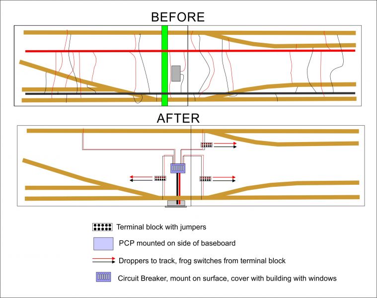 ,
, Based on Barry's track plan. Green is the scenic break. This about as easy as it gets (it can be made a lot more complicated) as you only have 4 power sectors. The PCP is now in the side, connected to the circuit breaker, in this case an NCE CB6, or you could use a 4 circuit electronic one from DCC Specialities. or 2 2 circuit ones. Use 14-16 gauge (1.63, 1.3mm diameter) from the PCP to the CB6, 18-20 gauge (1, 0.8mm) links to terminal blocks, then 20-22 gauge (0.8, 0.65mm) droppers to the track and switches, etc. I used red and black, use what ever takes your fancy but keep it consistent. Using terminal blocks means no stripped insulation, and keeps things neat and tidy. You would need 4 connectors between the 2 boards, use a Molex or similar, or even Power Poles.
Do some research and reading on circuit breakers, power sectors and their application in DCC. The CB6 is meant to work with the Power Cab, when there is a short it is protected and the sector affected lights up on the circuit breaker. The DCC Specialties units are much more flexible.
Nigel
©Nigel C. Phillips
Posted
Full Member
Hi Nigel. Thank you for your reply. I have said this before, “ I never seem to read anything all the way through “ and I am not proud of this fact. Although I have been able to read and write for a number of years. But AFAIK I have never wired a cross/ short circuit, as I have already stated,†each plank/ module works by itself “ it is only when the two are wired together that it goes wrong “. There is another thing, when I began my wiring, most if not all of it was labelled, alas not with a proper label, I fold over a piece of masking tape and write on that, colour coded number or letter. Best wishes Kevin
Hi Kevin,
Then you clearly have reversed the polarity between the boards. Check it out with the multimeter.
Nigel
©Nigel C. Phillips
Posted
Full Member
Staying on the thread Kevin.
Posted
Full Member
Staying on the thread Kevin.
Posted
Full Member
 Last edit: by Passed Driver
Staying on the thread Kevin.
Posted
Site staff
KevinHi Ron. Thank you for your message. Did you know that the UK was the first country to introduce decimalisation?But we couldn’t get on with it. Best wishes Kevin
Decimal measurements in 1585 by a Flemish mathematician
Decimalisation - Wikipedia
Decimal currency not by the UK but by Russia
Decimalisation - Wikipedia
Decimal fractions were first developed and used by the Chinese in the end of 4th century BC,[25] and then spread to the Middle East and from there to Europe.
Ron
NCE DCC ; 00 scale UK outline.
NCE DCC ; 00 scale UK outline.
Posted
Full Member
Staying on the thread Kevin.
Posted
Site staff
Cheers
Matt
Wasnie me, a big boy did it and ran away
"Why did you volunteer ? I didn't Sir, the other three stepped backwards"
"Why did you volunteer ? I didn't Sir, the other three stepped backwards"
Posted

Full Member
With information flying at him from everywhere, I'm not surprised he's confused - a total overload !
Let's all wait until we hear from whoever it is who's brandishing the multimeter.
Clear your brain Kevin and think about those far away hills and babbling brooks ………………….. :thumbs
'Petermac
1 guest and 0 members have just viewed this.