Fairford in 4mm EM gauge - the engine shed
Posted
#171287
(In Topic #9709)

Full Member
Scratchbuild in atyrene sheet
Background. I'm building a 4mm scale EM gauge layout based on Fairford, the terminus of the Fairford branch line from Oxford. The engine shed is the easiest structure on the layout, so that's where I started. The scratch build is in styrene sheet, although I may do the next one in wood. Two sheds will be required anyway, as I need one for the period 1900-1915 and another one, much weathered and dilapidated with a few broken windows, for the period 1955-1960. The prototype was a Brunel-design, apparently a hand-me-down, probably installed when the GWR absorbed the East Gloucestershire Railway in 1890. Long enough for 2 pannier locomotives, built of wood and with an asbestos-timed roof. Located at the end of the goods yard, it was barely visible from the station. Lighting was by oil lamp right up to closure in 1962.Reference source and materials. I used the plans in "Great Western Branch Line Termini, Volume One" by Paul Karau. No longer in print, the book contains plans scaled to 4mm/foot. No interior information, so a lot of guesswork is involved. The one photograph of the inside I have found was taken from the outside in bright sunshine, so difficult to see what was there. There was definitely a workbench running along the side (on the right facing the doors). There was an inspection pit that ran the length of the shed to within 4 feet of the back wall (Colin Moulden, FHS, personal communication). There was also a room that served as a staff/drivers mess at the end of the workbench until the wood was used to start the engine fires by the cleaners one cold and wet morning. After that a superannuated hose van located on the outside was used. Extrapolation and interpretation (as the historians like say in the absence of hard data) will be extensively employed for the interior. Styrene sheet, clapboard and strip were used to construct the walls (outsides done, insides currently in progress) and will be used in part for the roof joists and trusses (using information from other sheds, and which I'm just about to start).
Contruction. Nothing fancy, I am using a frame and double skin approach to minimize warping. For most of the construction a MEK-based glue was used, although I did resort to a styrene-specific glue(Humbrol) for long strips, as the MEK evaporated very rapidly. One thing I have found is that complete solvent/glue out-gassing takes several months. I have a solvent removal system that vents to the outside (a Heath-Robinson affair constructed from a bathroom exhaust fan, flexible clothes-dryer exhaust pipe and some cheap plywood) to minimize breathing any fumes when I am working. I have to make some side windows (16 in all) plus the end window above the entrance, as there is nothing available commercially. The choices are styrene strip (OK for the end window but too fiddly by far for the sides), laser printing (expensive), 3D printing (expensive) or metal etches (not too bad price-wise and I can get some nice 3D relief and have some of the windows open). And some doors of course. Real wood for those I think.
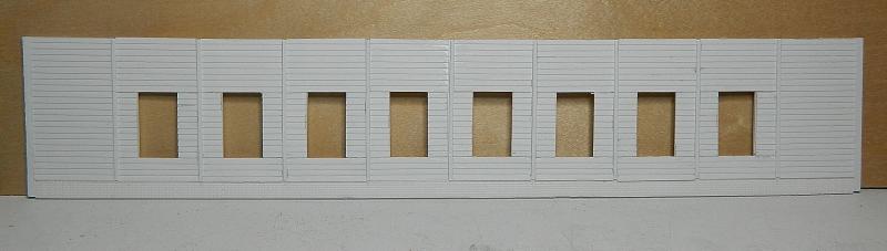
Fairford engine shed side. It's 14" long x 2.75" high. Each exterior panel is done separately. Deliberate differences in the bottom planks as this will be the weathered version. No joins in the bottom brick section.
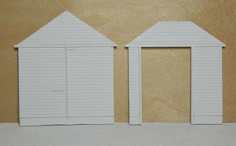
Fairford engine shed ends. The truncated entrance had a window at the top, which is being built.
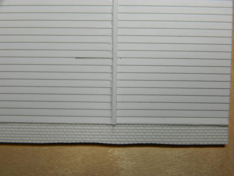
Fairford engine shed side detail. Only 5 courses of brick will be visible, the rest will be below the surface.
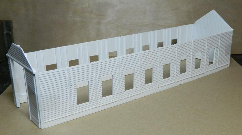
Fairford engine shed showing interior frame construction. Held together with tape for the photo.

Fairford engine shed side view. Rear end has interior vertical plank skin in place. Note variations in bottom planks.
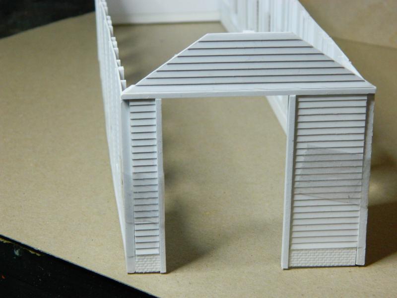
Fairford engine shed entrance.
That's it for the moment, I'll finish the interior walls, and make a start on those roof joists and trusses. Plus I'll have to start thinking about the smoke collection system and chimneys.
Nigel
©Nigel C. Phillips

Posted

Banned
Good looking engine shed so far, looking foward to future updates. Question, how much internal detail are you doing, ie wall frames ?
Cheers, Gary.
 Last edit: by Gary
Posted
Full Member
The plan is to have visible supports on the wall for the roof trusses (brass to give rigidity, and I may yet solder-up the trusses), the workbench with the usual assortment of tools, vices, etc., the mess room at the back, inspection pit, couple of oil drums on the bench (lubricating, steam). Couple of LED's for the oil lamps. That's it. Fairford was an Oxford sub-shed, anything major would have been done there. Basically stabling for the 2 engines based at Fairford overnight. As I said, interpretation and extrapolation are the orders of the day on this one. No plans to have a demountable roof, just a demountable shed!
Nigel
©Nigel C. Phillips
Posted
Full Member
The shed has been in storage for a year, I finally found it and have started to do a bit more work. Roof trusses done, inside piers in place, made a start on the windows. Double walled for stability, although I think some brass angle stabilizers top and bottm will be required (it's 14" long and a bit bendy). Guesswork regarding the interior, no photo's found. Bench at least on the RHS (just visible in photo's) plus a small coal bin, steam oil drum, grase drum. Oil lamps were the order of the day until the line closed, so some soft yellow LED's. Inspection pit needs to be planned as well. Needs to be long enough for 2 0-6-0 panniers. Concrete or wood floor?
Pictures show the progress.
Nigel
.
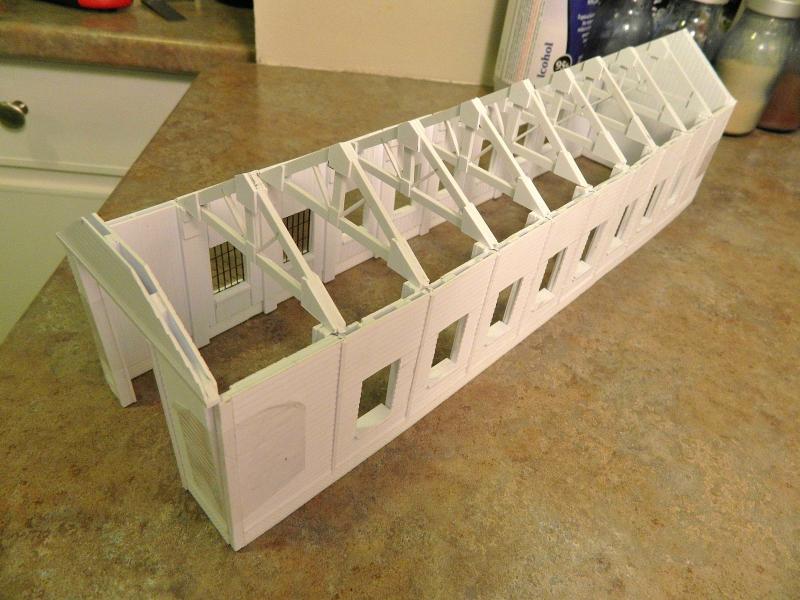
Shed roof trusses. Approximately 10" x 3" beams. This was an old IKB shed that was brought to Fairford probably in the 1880's.
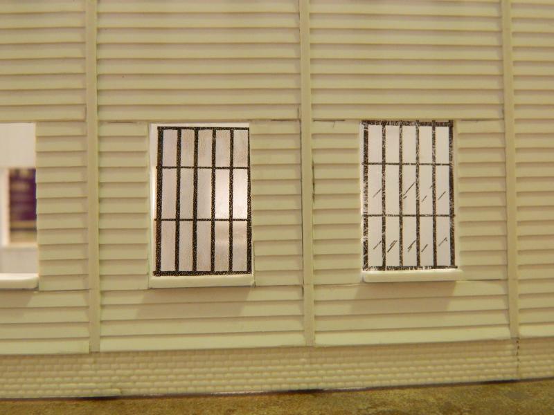
Shed windows. No expense spared here. Propped in place for the moment until I decide on clear (right) or mucky (left). Probably mucky, this is 1961 and the shed is over 60 years old. Brick foundation is SE finecast sheet. Bottom 2 rows will be buried.
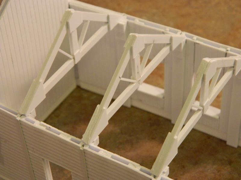
Truss detail. Built more for stability than appearance, I didn't fancy soldering-up 9 in brass. Strengthening gussets at sides and top. Piers will be skimmed with SE Finecast brick.
©Nigel C. Phillips
Posted
Full Member
Andrew
Posted
Banned
They do look as if they have been beefed up, or maybe it is because the single road engine shed make them look heavier. Regardless, it is a great model. Looking foward to seeing more soon.
Cheers, Gary.
Posted
Full Member
Roof trusses are almost certainly overscale - 6" by 12" and 3" x 6" for the laterals. Brass and a fair number of solder spots (6 per truss) versus beefy styrene, styrene won. The roof will be quite substantial, so I want something that will not sag.
I've seen photo's of wood beams in engine sheds that look around 4" by 12", bit too wavy in styrene. They're not visible with the roof on, so I went for function not form.
The major issue I'm looking at is bendy sides. This is a long shed - 14", so I'll need something top and bottom to keep the walls parallel. The top especially, as the bottom will be held in place by the base inside and the ground outside.
Nigel
©Nigel C. Phillips
Posted
Full Member
Thanks, it's been a long project. End is in sight for the engine shed, good shed and station are next. With the reduced space available I was going to cut it in half, but if I can store one 5' x 1.25' module in the model railway room (5' x 4.75') I can store two. Add the fiddle yard and it all works as a mini Fairford, albeit with a lot of compression in the yard, some sharpish turnouts (short switch blades and a fairly tight radius, thank goodness for Templot) and reduced station platform length. More on that latter when the track plan is finalized.
Nigel
©Nigel C. Phillips
Posted
Inactive Member
Posted
Full Member
Good idea. If the brass angle doesn't work some wood might. The workbench side is not a problem, a long bench down the side of the wall will keep the wall in place. It's the other side that needs bracing. My plan at the moment is to run brass angle (1/8") along the top and to anchor the bottom to the floor. Still haven't decided on wood or concrete. Bit more research.
nigel
©Nigel C. Phillips
1 guest and 0 members have just viewed this.