Turntables and RR & Co
Posted
Full Member
The diagram shows a DC supply, and NOT the DCC bus!!!! This suggests that the switch includes a rectifier to change the incoming alternating waveform from the DCC bus to DC.
If the diagram is correct, then if you connect the red wire directly to the positive of a DC supply - I presume 12v will be fine - and then connect the yellow to the negative of that DC supply, the motor may turn in one direction. If it does not, then also connect the grey wire to the yellow wire. If the motor does run without the grey connected, then it should stop when you connect it to the yellow.
I say that, because I cannot tell from the diagram whether connecting the grey to the yellow starts the motor, or stops it.
To get it to turn in the other direction, swap the red and yellow wires at the DC supply, and then do the same as before with the grey wire - still connecting/disconnecting with the yellow.
What I interpret from the diagram is that a DC supply is being fed to the motor through the Red and Yellow wires, and then the connecting/disconnecting of the grey wire to the yellow is starting or stopping the motor - this may be some form of internal contact arrangement for the motor, or it may be that the motor does NOT have a permanent magnet like you are used to in your locos, but instead, requires a permanent DC voltage (from red and yellow) for its field coil, and then has its armature switched in and out by the grey wire connecting to the yellow.
If this works off a DC supply, then we can consider what you need to make it work off the DCC power bus.
 Last edit: by Geoff R

Posted

Full Member
That makes perfect sense…..why didnt I think of that.
 . I have to go out for most of the day but will try it as soon as I get back
DCC will not be a problem. If the table turns it will be told to do so by input from the DCC bus into the LS150 which will fire the relay
I have some mechanical (?) relays which are 4 pin so I can feed the DC power for the motor into two and the DCC for the bridge track into the other two………if I need to (with another relay for the yellow grey as shown)
The table is going at the end of the fiddleyard there and are only two movements……….Locos enter from the arrival road the TT turns clockwise thru 165o and they exit via the departure road…………..the TT either clockwise 15o or anticlockwise 165o to index the arrival road ready for the next loco……………….if I use the latter solution ……the Great Way Round
 I can match the bridge track polarity switching with the motor switching
However I am wondering if I need to power the bridge track at all other than by contact with the entry and exit track
Will get back to you later…….many thanks for your help
Kind Regards
Posted
Full Member
I squeezed in time before my meetings and quickly wired it to a 12v DC Transformer……….Grey and Yellow start the motor…..remove the Grey and the motor stops
I just have to play with switching the polarity of the input to change the direction of turn……….wire up the relays…..hook up the LS150 and get it going in RR&Co where hopefully I will be on safer ground!
Because of the way I plan to operate I dont think I will need the reeds after all….time will tell
Once again many thanks Geoff…………I know……elementary my dear Watson:oops::oops:
Incidentally thank you for that wiring diagram for a 3 way that you posted on another thread…..that will shortly save me a load of fret
Kind Regards
Posted
Full Member
Pleased to be of help.
As for powering the tracks on the table, I would be trying to have them fully powered while it is turning if you can. That way any sound equipped loco will keep its sound going while the table is turning. If you want to use a relay to change the polarities rather than an automatic reverser module, then I guess that you would just do so at the end of a the 165deg turn. (Hopefully the relays will move over quick enough not to worry any sound chips - Max may know more about what is possible?)
Posted

Inactive Member
I understand that the Zimo decoders have dealt with this issue by using a capacitor, but I'm not up to that bit in the book. :oops:
Max
Port Elderley
Port Elderley
Posted
Full Member
I shouldn't be hijacking John's thread, but how do you do that with the Loksound, Max. All the Bachmann and Hornby sound locos I have are using Loksound 3.5s so I would like to do the same thing if I can. By the way, Lenz also use a capacitor as an add on attached to special pads on their Gold decoder.I've got a Cornerstone 130 foot with all of the bells and whistles and even it pauses the sound as it passes the changeover place. I've set up my Loksound decoders to resume what they were doing after a power interruption. The sound goes off momentarily and comes back on again. QSI and Tsunamis have it built in, so it shouldn't be a problem.
I understand that the Zimo decoders have dealt with this issue by using a capacitor, but I'm not up to that bit in the book. :oops:
Posted
Inactive Member
The second last pane on the Lokprogrammer does it.

Check the top four.
Max
Port Elderley
Port Elderley
Posted
Full Member
Sadly I dont have to worry about sound…….I am far too deaf….too much competitive shooting in my youth……so sound is like working semaphores…….not an option on Granby III
The plan is to have a RR& Co schedule: Block Arrival via Block TT to Block Departure
A schedule specific operation will invoke the Turntable Command "move clockwise to next stop" when the loco stops in Block TT and then at the finish of the schedule a second TT command will " move anti clockwise to next stop"
I believe these commands will be the same as pre setting a point……ie the LS 150 will send a burst to throw the relay…….although thinking about it if I power the bridge I may have to build in a delay and that would mean a third relay?
One step at a time……tomorrow I will wire it up properly and report back
Cheers
Posted
Guest user
Further to the hijack. If you don't have the LokProgrammer you can set a LokSound chip to ignore (some) interruption by setting CV 124 to a value of 6. This sets two bits in the CV to tell it to maintain its state and also continue at last set speed. This helps a lot with power interruptions resetting the sound state.[user=269][/user]I shouldn't be hijacking John's thread, but how do you do that with the Loksound, Max. All the Bachmann and Hornby sound locos I have are using Loksound 3.5s so I would like to do the same thing if I can. By the way, Lenz also use a capacitor as an add on attached to special pads on their Gold decoder.
Cheers
Dave
Posted
Full Member
" thread. When I am in similar situations with relays or other electronics that is not doing what I want it to do, I usually work with two or three crocodile leads. (wires with clips on each end if the term does not translate). I would try disconnecting one or two leads at a time, and "hard" wiring to check things out.For example:- hard wiring the red and yellow as a pair to the DC supply and then just using the relay on the grey to start and stop the table will give a degree of info about correct working. Swapping the supply around to the red and yellow (ensuring that the yellow always also goes to the "grey" relay, should give you direction of turn change.
When that is sorted, I think I would forget about the grey relay and hard wire the grey to the yellow - which should make the table turn continuously - and then try to operate the latching relay from TC (or even from the Lenz) to make the direction change. There should not be any problem doing that whilst it is rotating as it is an electrical change, not a mechanical one.
Happy to discuss further if you wish.
Posted
Full Member
I was going to email you but then decided that I was using antiquated relays…….I have to leave right now but will post a photo and chapter and verse when I get back in about an hour
Kind Regards
Posted
Full Member
I am attempting to use 2 relays that I bought many years ago for an abortive train detection system. I think they are 4 pole but I am attempting to use them as double pole and single pole…….which may be the problem
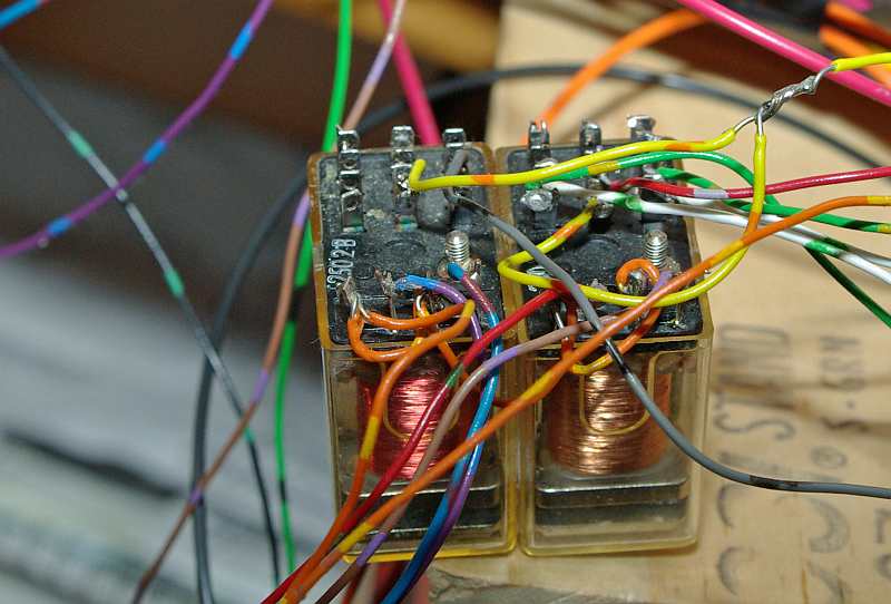
They are single coil
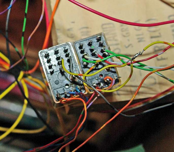
As you can just see the pins are numbered…….from the top
16 9 10
14 15 8
13 6 7
11 12 5
* 5 pin has a mark under it??
4 3 2 1
To a bumbling amateur like me it looks like an advanced form of Sudoko.
Anyway this is what I have worked out
Contacts 1 - 4 are like the contacts on a point motor………4 and 2 are common and 1 and 3 are connected to the + and - outputs on Point "A" of the LS 150 Point Decoder.
By trial and error I have deduced that 5, 6 and 7 are a set…..similarly 11, 12 and 13
13 DC + 6 Red 7 DC -
11 DC - 12 Yellow 5 DC +
When I tested this seemed to work in that when I threw the notional point A with the Lenz controller the polarity of red and yellow changed………………….there is no current on any of the 6 unconnected contacts
On the second relay I connected the Yellow to 6 and the Grey to 7 and again this seemed to work in that I could turn the TT on and off from the Lenz Controller…………..incidentally I have checked connecting the grey directly to the yellow and that does start the TT
I understand the logic of the Fleischman switch as:
Turn it to the left and polarity for Red and Yellow is set for CW rotation and Grey is connected to Yellow and TT turns CW
Turn it back to Centre and the G Y Connection is broken and the TT stops
Turn it to the right and polarity for R and Y is set for ACW rotation and GY are connected
RR&Co attempts to emulate this so that when you click the CW button in the TT Window Point A is thrown setting the polarity and then Point B is thrown starting the TT
Press the stop button and only Point B is thrown breaking the GY connection
Separately using the Lenz Controller the relays seemed to do what they should but once I started using them through RR&Co I started getting "unexpected" results…..ie pressing the stop button would not stop the TT….. I had to press the start button and so on
When I went back to testing I found that throwing Point B would not always start the TT and the polarity of Grey would remain unchanged…….similarly with Point A……one could throw the point a couple of times and the polarity of Red and Yellow would remain unchanged
I do wonder if my yellow connection is correct…..you can see it on the photo; I run it from both relays join it together then send a single yellow to the TT……could this be the issue?
Failing that……..I have wired the relays incorrectly
The relays arent working
They are the wrong relays
Hence my decision to take a break and buy two new solid state relays as specified by RR&Co …..they are only a few bucks and although retired I still put a notional value on my time
Having said that I see I have just written an essay:roll:
Any help or suggestions appreciated:oops::oops::oops::oops:
PS The soldering isnt great but I am satisfied nothing is touching
Posted
Full Member
As latching relays, they will need only a pulse on each coil to turn on or off. When you tried it from the Lenz, were you just pulsing the decoder?
If you disconnect from the decoder, can you make the relays work by momentarily connecting 12v across first one coil and then the other?
Last edit: by Geoff R
Posted
Full Member
When I first started trying to work it out I hooked up 2 and 4 to the common of my point bus then I just momentarilly touched either 1 or 3 with the positive wire from the point bus. I could hear the relay buzz and could measure changes in polarity…..but I probably didnt do it systematically enoughIf you disconnect from the decoder, can you make the relays work by momentarily connecting 12v across first one coil and then the other?
Then I hooked it up the decoder and activated it with the Lenz controller just like any other point…..I get a buzz every time but not always a polarity change…….does that mean it isnt latching?
As latching relays, they will need only a pulse on each coil to turn on or off. When you tried it from the Lenz, were you just pulsing the decoder?
There is only one coil per relay…..is that the problem?
It has to work like a twin solenoid point motor…qiuck burst one way and the polarity changes I assumed with 6 contacts that would work even though there is only one coil
Thank you for your patience on this Geoff :cheers
Posted
Full Member
I would start with trying this again, John, but with the contacts connected to the TT and the 12v DC supply as you already have them. Just unplug or disconnect each relay from the decoder outputs. Connect the grey and yellow together to get the TT moving without having to worry about that relay, and then do the momentary touching on the other relay to see if the TT changes direction. If it does, then the relay is working fine. If it does not then the relay may be a problem.When I first started trying to work it out I hooked up 2 and 4 to the common of my point bus then I just momentarilly touched either 1 or 3 with the positive wire from the point bus. I could hear the relay buzz and could measure changes in polarity…..but I probably didnt do it systematically enough
I don't think so, because there are 4 contacts. I suspect that one coil is wound inside the other in the opposite direction, so to the eye you only see a single coil. Because one is wound the opposite to the other, it will energise the armature in the opposite direction. I presume there is a simple mechanical latch which the energy in the coils overcomes when they are powered.There is only one coil per relay…..is that the problem?
Your assumption is correct. The number of contacts does not matter at all. I remember "playing" with early telephone exchange equipment where there were a dozen or more contacts on a single relay.It has to work like a twin solenoid point motor…qiuck burst one way and the polarity changes I assumed with 6 contacts that would work even though there is only one coil
Only to happy to try to help. I find it quite fascinating trying to work out a solution to a problem someone has more or less the other side of the planet, and who I have never met, but with whom I share a similar passion. In this case trying to control a model railway with a few electronic components and a computer program.Thank you for your patience on this Geoff :cheers
Posted
Full Member
I think we have narrowed the problem down to the on off relay
Touching the yellow with grey (hard wiring) causes the TT to always start in the required direction:thumbs
Touching the contacts on the first (polarity change) relay cause the TT to consistently change direction as anticipated :thumbs
Touching the contacts on the second (on/off or Yellow Grey) relay causes inconsistent results (an understatement:roll:)
Sometimes the designated start wire will start and the designated stop will stop…….other times two applications of the stop wire are required (even though the relay is activated twice) other times the start wire will cause the TT to change direction ie the Red and Yellow Polarity are changed even though Red is not associated with this relay:roll:
So that would tend to suggest the relay doesnt like operating in single pole mode…………..I find it hard to believe that the TT cannot cope with the input from 2 relays after all I am just carrying out the set up printed in RR&Co albeit with Heath Robinson relays
I may try another relay tomorrow (I have a few) but I am inclined to think I should just get the right equipment.
As we used to say in the 8th of Foot ……Nec Aspera Terrent………..
Posted
Full Member
Indeed, I had. 8hrs ahead made that 1:30am for me - well in the land of nod!You have probably gone to Bed by now…..its only 5.30pm here
Good bit of fault finding. It does seem like the on/off relay is faulty - maybe sticking.I think we have narrowed the problem down to the on off relay
Touching the yellow with grey (hard wiring) causes the TT to always start in the required direction:thumbs
Touching the contacts on the first (polarity change) relay cause the TT to consistently change direction as anticipated :thumbs
Touching the contacts on the second (on/off or Yellow Grey) relay causes inconsistent results (an understatement:roll:)
Sometimes the designated start wire will start and the designated stop will stop…….other times two applications of the stop wire are required (even though the relay is activated twice) other times the start wire will cause the TT to change direction ie the Red and Yellow Polarity are changed even though Red is not associated with this relay:roll:
So that would tend to suggest the relay doesnt like operating in single pole mode…………..I find it hard to believe that the TT cannot cope with the input from 2 relays after all I am just carrying out the set up printed in RR&Co albeit with Heath Robinson relays
I may try another relay tomorrow (I have a few) but I am inclined to think I should just get the right equipment.
The changing of the other relay sometimes while operating the on/off relay could be due to electrical noise - commonly called spikes - which will occur as the power is removed from the relay coil. A voltage spike equal to the voltage applied to the coil occurs, but in reverse so it appears on top of the 12v rail - making a 24v spike. It won't last long, but it could easily be enough to fire the adjacent polarity changing relay. This is a physical property of a coil, so it is nothing to do with the relay being faulty. You can stop it happening by connecting a diode (like a 1N4000 series) across the coil opposite to the normal flow - i.e. cathode connected to the plus 12v connection and anode to the 0v connection. I am not sure which connection you have permanent and which is switched?
There is nothing wrong at all with only using a single pole - the contacts are controlled by the relay armature but their use does not affect its operation. I suspect that the latching mechanism may have got "sticky" over the years and that is causing the irregular performance. Another may be fine - as proved by the polarity changing one.
As we used to say in the 8th of Foot ……Nec Aspera Terrent………..
It wouldn't be half as much fun if it was easy.
Posted
Full Member
The changing of the other relay sometimes while operating the on/off relay could be due to electrical noise - commonly called spikes - which will occur as the power is removed from the relay coil. A voltage spike equal to the voltage applied to the coil occurs, but in reverse so it appears on top of the 12v rail - making a 24v spike. It won't last long, but it could easily be enough to fire the adjacent polarity changing relay. This is a physical property of a coil, so it is nothing to do with the relay being faulty. You can stop it happening by connecting a diode (like a 1N4000 series) across the coil opposite to the normal flow - i.e. cathode connected to the plus 12v connection and anode to the 0v connection. I am not sure which connection you have permanent and which is switched?
Thank you for such a clear explanation Geoff you do make it possible for me to grasp some of the logic of all this. The spike makes a lot of sense because it would account for the TT starting occasionally when I change polarity. The sticking would account for the random affect
Would it help if I separated them and set them further apart…..say 3'?
If not I am afraid I will need some help with the diode …..
[1] Could you amplify on the 1N4000 desription. I believe I have a variety of Diodes acquired over the years but I dont know which is which other than by colur and stripes:oops::oops:. I use them in the LS150 for the output to the Tortoi……would they do?
[2] Which end is the cathode?:oops::oops::oops:
[3] I would need to put 2 diodes on both relays ie 4 diodes in total ?
There is nothing wrong at all with only using a single pole - the contacts are controlled by the relay armature but their use does not affect its operation. I suspect that the latching mechanism may have got "sticky" over the years and that is causing the irregular performance. Another may be fine - as proved by the polarity changing one.
I will try another relay later today
It wouldn't be half as much fun if it was easy.
True but the ratio could be corrected right now
Once again many thanks
Kind Regards from a very snowy Vancouver
Posted
Full Member

The diode you need is like the one on the right, not the one on the left as that type is not powerful enough to discharge the spike. It is a bit like a capacitor discharging, but in this case it is an inductance - the coil. The Cathode should be indicated by a band on the body like the one in my picture. This is the end that needs to go to the positive end of the coil. In my little circuit diagram, when the switch is opened, if there were no diode, that end of the coil would go up to 24v, but with the diode, it is limited to about 12.7v with the diode taking current to disperse the "energy" that would have been in the spike.
Yes you will need to do this across each of the two coils on each of the two relays - 4 diodes altogether. Be careful to get them the right way round. If you get them reversed, they will simply conduct and act as a short circuit across the coil. I suggest that you check the relays work after fitting just one diode at a time, and do it by touching a wire to the open end of the coil like you have been doing to test things, and NOT with the decoder attached. Then, if you do get a diode the wrong way round, you will just short out the power supply and not damage a decoder output - hopefully you are using a supply with some output protection??
By the way, separating the relays might help a little, but a lot of energy is released when the switch opens, so the generated spike can cause interference for quite a distance. I fit supression diodes to all of my relay circuits. If any logic chips are nearby or running of the same supply they are essential.
Posted
Full Member
That was quick……….I have just checked and the diodes I use on the LS150 are 1N4001 so they will work
Your comment about circuit protection was very timely. My main power bus is well protected as I all too frequently notice! However I have a separate power bus for points and that is unprotected……..so I should address that ASAP……..I dont think I need anything as sophisticated as the DCC Supplies Breakers that I use but some form of re settable breaker immediately downstream of the transformer……..have you any suggestions.
Something bizarre happened last night with the TT which I forgot to tell you about. In the railway room all the power transformers are on a powerbar so at the end of a session I have this routine where I turn the power off from RR&Co, save and close RR&Co and finally turn the Power Bar off.
I Did all this about 5.30 last night after my abortive testing and went upstairs to email you……..about 7pm when we were having dinner my wife said there is a funny noise downstairs and it isnt the washing machine……….downstairs I go……and the TT is merrily turning round and I suspect it had done so since 5.30!. It is at the other end of the room by the door and has an independent 12v DC supply (once finalised I was going to fit a switch and light as a reminder) Either it physically stuck and became unstuck or this is further confirmation of the sticking relay!
I will try and report back before your bed time!
1 guest and 0 members have just viewed this.