Turntables and RR & Co
Posted
#114851
(In Topic #5983)

Full Member
I am trying to get my head around the logic and feasibilty of setting it up
There is a wiring diagram in the TC help section and shortly I would appreciate some help in understanding the relays required to control direction of travel and polarity
But for now I would like some advice on hooking up IR Dots to my Lenz System.
I want the turntable to operate automatically and stop at a designated exit road……I understand exactly how to do that with RR&Co using TC switches and a flagman…………but the flagman has to be triggered by something which tells it the bridge has arrived, or is about to arrive, at the exit
The RR&co forum talks about Reeds and Magnets but I am not keen on that and wondered about IR dots so:
[1] Could I set up an IR Dot to track the arrival of the bridge (I realise that I would need an IRdot for each exit)….any ideas on how I coud do that physically?
[2] If so….this is probably a dumb question but how do I hook it up to my Lenz System………can I feed it from the Power Bus and hook it up to one of the 8 contacts on an LB101 feedback controller……then it would have an address that TC would recognise just like any other contact indicator
Kind Regards

Posted
Full Member
The IRdots are fairly simple devices. The main output is an open collector transistor which closes to ground when something is detected by the IR pair. That should work as you suggest, provided that you can position the detection pair so that they only detect when the TT is in the correct position. Not sure at the moment how you would do that, as they would detect the TT well, unless you drilled holes in the well and poked the detectors through so that they normally had nothing above them, until the table deck turned over the top of them.
Sounds like an interesting project.
Posted

Inactive Member
I've got a Cornerstone indexed turntable, so I can see how they work. Good luck with it. The Cornerstone has only one detector. It looks like a light sensitive LED, and the turntable calculates the stopping position from an initial self calibration procedure. There is also a "dead" spot at right angles to the detector, where the rails on the bridge change polarity. As it passes this spot, the sound and lights go off and on momentarily.
The decoders are set to resume the same commands in the event of a power stoppage, so that's not a problem.
The Cornerstone turntable is able to be operated by a decoder, although mine is still manual at this stage. At the moment it's a very expensive (A$450.00), icon in a diorama around the roundhouse.

I hope some of that helps.
Cheers
Max
Port Elderley
Port Elderley
Posted
Full Member
The LB 101 is described as a feedback controller and is normally used to collect the input from LR 101 occupancy detectors
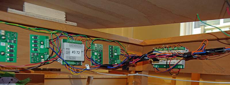
Its the one labelled #3 72. The occupancy detectors (4x2) are on either side of it so there are 8 individual connections (ie contact indicators for blocks) at the top plus a common (green)……is that what you call "ground" ?…………sorry to be so dumb
At the bottom it is powered separately from the point bus (orange and blue) and the only other connections are to the Lenz Xpressnet (Brown and Yellow)
I am assumming that the IRdot has 4 connections…..2 for power (from the track or point bus) and two for feedback so I would connect to the green common and one of the available 8 individual connections and when the bridge is detected the circuit wold close and this information would be fed back thru Xpressnet……….sorry to go on but I find it helps if I write the sequence down
I would prefer not to drill the TT Well……RR&Co has a command to stop at the next exit so I wondered if I could mount them vertically prior to each exit………..I will worry about disguising them later!
 Last edit: by John Dew
Posted
Full Member
Thanks Max. The Fleischmann isnt indexed which is why I need some form of detection.I've got IRDOTs on my level crossing, John. These ones rely on reflection from the bottom of the loco as the pair are set up between the rails. I have found them to be unreliable, as one loco will set them off and another identical loco will not. I've tried several kinds of reflective tape, paint and silverpaper under the locos; but they remain as perverse as ever.
I've got a Cornerstone indexed turntable, so I can see how they work. Good luck with it. The Cornerstone has only one detector. It looks like a light sensitive LED, and the turntable calculates the stopping position from an initial self calibration procedure. There is also a "dead" spot at right angles to the detector, where the rails on the bridge change polarity. As it passes this spot, the sound and lights go off and on momentarily.
The decoders are set to resume the same commands in the event of a power stoppage, so that's not a problem.
Polarity change is a separate issue ……..there is a wiring diagram that is supposed to deal with it but I am afraid I am a bit thick:roll: …….I will be asking about that shortly
So there is your next R&RCo project……dont wait for your box cars……get cracking!The Cornerstone turntable is able to be operated by a decoder, although mine is still manual at this stage. At the moment it's a very expensive (A$450.00), icon in a diorama around the roundhouse.

Posted
Inactive Member
Max
Port Elderley
Port Elderley
Posted
Full Member
Posted
Full Member
I have looked up the LR101 and I see that it requires a non-current carrying contact for its inputs. That is not what the open-collector (a transistor) provides, but for a couple of £ more, Heathcote sell an IRdot with a relay on board which will give you a simple switch contact which should be fine for the LR101.
I am not sure about mounting the detectors vertically above the turntable deck, though. They are quite sensitive. They will operate in a tunnel, however, provided that the roof is black so as not to reflect too much of the infrared. Might be best to get hold of one and experiment a bit. You can buy them with the detector on a flying lead instead of attached to the board, which might suit you best.
How do you control the TT currently? How do you get the tracks aligned?
Posted
Full Member

I fitted a small bar magnet under each end of the deck as shown above.

Then I fixed a reed switch to the outside of the well. Only a crude set up, but it worked faultlessly. The beauty of it was that everything was hidden. The reed has a very narrow operating range, so it would be easy to set several up alongside each other for different exit roads. If you are going to add some intelligence within TC, then it perhaps does not matter how accurately you fix each reed as you could perhaps make "adjustments" within the TC setup?
Last edit: by Geoff R
Posted
Full Member
I bought the TT secondhand about 15 years ago and used it briefly on Granby II (DC) …….when I dismantled that layout I kept the shed module intact in the hope of incorporating it into Granby III (circa 2013) but recently decided that wouldnt work so I have dismantled the module and rescued the TT and am now raring to go on another distraction:roll::roll:
The tracks automatically align …..its quite neat
Thank you for being being so patient with me on the wiring…….and I do appreciate you taking the time to post the photos
You now have me thinking that the reeds/magnets might be a better option……that is what Pete Turvill uses on the RR&Co Forum ………….but I guess the reed is current carrying so I would still need to send the signal to the LB 101 through a relay?
I have only just discovered TT and RR&Co when I was started I used the "need to know" philosophy and skipped the entire section…………..now I have read it and played a bit with the screen it looks very powerful…..lots of potential once I overcome the initial hurdles
Kind Regards
Posted

Full Member
I put the control problem to an electronics supplier we use at work, we had a discussion over it and came up with a plan.
The motor for the TT would be driven by a timer board he designed which would be fed from track AC via a loco decoder.
Detection was by a single magnetic reed switch at the mouth. My turntable was only for turning the locos so there was only one road in. As the timer board detected the alignment it basically cut the power to the motor to stop the bridge. After teen seconds the timer board reset ready for the next rotation. The speed of the bridge was controlled by the loco decoder (a cheapy Bachmann).
I was going to use TC to control and time the rotation of bridge and allow a couple of seconds over so.
Thats as far as i got never got it fitted.
Simples really.
Not too impressed with the strength of the PECO TT though was condsidering the new Heljan ready built and balanced.
Pete
Regards
Pete.
ECOS2 with RR&Co Traincontroller and a load of other electronics so i can sit back and watch the trains go by.
Pete.
ECOS2 with RR&Co Traincontroller and a load of other electronics so i can sit back and watch the trains go by.
Posted
Full Member
So a couple of years ago, I bought the Heljan. It is wonderful. I have designed the electronics to drive it from DCC, but not got around to building it, so I still push the button - but it is great to watch it turn and align.
John - if your table aligns automatically, what is the detection for? A reed switch will be fine as an input for the LR101, you wouldn't need any relays.
Posted
Full Member
Peco needs balancing and micro bearings fitting to be reliable for auto operation and that was something i would considered.
I think the Heljan is the way to go if i can find a place for it. The new DCC version seem s to get rave reviews.
Pete
Regards
Pete.
ECOS2 with RR&Co Traincontroller and a load of other electronics so i can sit back and watch the trains go by.
Pete.
ECOS2 with RR&Co Traincontroller and a load of other electronics so i can sit back and watch the trains go by.
Posted
Full Member
The other big thing is the connections to the deck rails. The original just has copper circles under the deck which rub on wipers in the well. It works very well! and makes a solid connection except that there is a break to allow for reversing the rail polarities. That would not be necessary for DCC provided the track was driven from a reverser. I cannot see how to modify the original, because it really needs a copper circle for each rail rather than the two halves fitted.
If you see one, please take a look under the deck to see. If it is still a split ring, then sounds will stop during a full turn.
Posted
Full Member
http://www.youtube.com/watch?v=FznsQj7Z-JU
Regards
Pete.
ECOS2 with RR&Co Traincontroller and a load of other electronics so i can sit back and watch the trains go by.
Pete.
ECOS2 with RR&Co Traincontroller and a load of other electronics so i can sit back and watch the trains go by.
Posted
Full Member
One of the comments added does say that the tracks still have a split ring feeding them, which is a shame, but I guess that would have required re-work to the mechanical side of things as well as the change to the control electronics. It has got me thinking again about converting mine.
Posted
Full Member
[user=422]Geoff R[/user] wrote:
I want to be able to tell it to stop at a specific exit (even though I am only planning 3). The plan is that a schedule involving exit 1 would turn on a TC switch. The reed will trigger a flagman so when flagman 1 is on if switch 1 is on it will stopJohn - if your table aligns automatically, what is the detection for? A reed switch will be fine as an input for the LR101, you wouldn't need any relays.
Thanks for the advice about reeds….thats great….. now I just have to sort out the operating wiring. TC suggest operating the fleischman thru two sequential outputs of a point decoder which fire a Double Pin latching relay to control direction of travel (and polarity?) and a second single pin relay to turn on and off the TT motor……I may need help with this:roll: I am going to try and work it out on my own first but I suspect you will be hearing from me
The Heljan looks very interesting and as I understand it has a DCC address for each desired exit so it should be very easy to operate with TC. Incidentally it is the same as Walthers Cornerstone except it has some sort of US structure at midships on the bridge……….they are quite expensive but there are some deals where they are a lot cheaper than the Heljan…..I have seen $200!!! When I build the shed (2013) I will put one in as a second table
Kind Regards
Posted
Full Member
I shall watch with interest. Just shout if/(when) you need help with the latching relay circuit.Thanks for the advice about reeds….thats great….. now I just have to sort out the operating wiring. TC suggest operating the fleischman thru two sequential outputs of a point decoder which fire a Double Pin latching relay to control direction of travel (and polarity?) and a second single pin relay to turn on and off the TT motor……I may need help with this:roll: I am going to try and work it out on my own first but I suspect you will be hearing from me
I think the Heljan may be exactly the same as the Walthers because the "sort of US structure" came with mine as an optional add on part - it is still in the box!! The new one is on sale in the UK for £200 !!!!!The Heljan looks very interesting and as I understand it has a DCC address for each desired exit so it should be very easy to operate with TC. Incidentally it is the same as Walthers Cornerstone except it has some sort of US structure at midships on the bridge……….they are quite expensive but there are some deals where they are a lot cheaper than the Heljan…..I have seen $200!!! When I build the shed (2013) I will put one in as a second table
Posted
Posted
Full Member
The turntable has two sets of wiring as does the switch which powers the motor and controls the direction of travel
The turntable has 2 wires which supply power to the track on the bridge……for now we can ignore this ……it works and I know how to switch polarity
The second Turntable set…. 3 wires…..Red, Yellow and Grey is connected to the Red, Yellow and Grey wires attached to the switch.
Connect the remaining two wires on the switch to the DCC power bus………………turn the switch clockwise……and the turntable moves clockwise….release and it stops. Anyiclockwise it moves anticlockwise
I want to discard the switch and turn the Table automatically by using a relay as per this diagram printed in RR&Co Help: Fleischmann Turntable
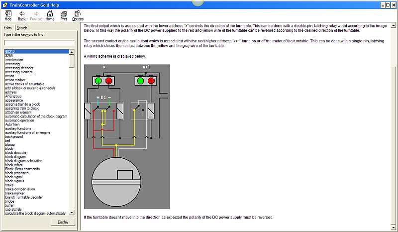
Its not a super clear shot but the idea is to use a double pin latch relay to control the direction of travel and a second single pin relay to turn the motor on and off
I have got the relays to work after a fashion……ie output from a point decoder will switch polarity however I cannot get the motor to work:twisted: I assumed I just needed to find some combination of the three wires (the switch is a sealed unit) and from the wiring diagram I yellow and grey looked the best bet, to comnnect to the power bus…………..but no luck
With the switch connected it works……..if I eliminate the switch and try and to power up the motor directly (no relays) using red, yellow and grey in combination with the power bus……nothing
Very frustrating…….amateur that I am, it should be simple……….is there some sort of electronc gizmo in the switch that I am missing?
Any help, suggestions, work arounds much appreciated
1 guest and 0 members have just viewed this.