Whatsthename new OO steam DC terminus
Posted

Full Member
Layout blog
[user=606]Sol[/user] wrote:Once again Sol, you have the answers! The issue of the Dremel body size has bugged me in the past, this looks to be ideal.For cutting rails as baseboard joins, I use one of these to add to my dremel
https://www.ebay.com.au/itm/163983817550?hash=item262e327b4e:g:tHQAAOSwai5d8LkX&frcectupt=true
Any ideas on where to find the Dremel holder?
Thx
 Last edit: by Colin W

Posted
Full Member
Hi Roger,….. And finally progress today
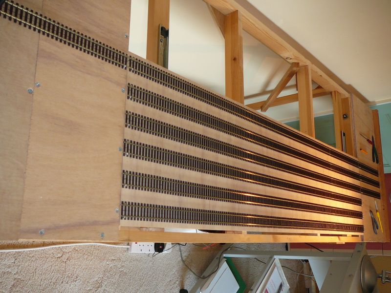
I'd not looked at your plan carefully enough before, now I see the setup in the flesh I've really warmed to it rather than using a radial Sector plate.
The one issue I was wrestling with was the need to have a vacant track in the transverser to effect the move. I guess during operations it will be normal for another train to move out first, freeing up the lane you need. If so do you need the stub tracks at the front end?
Colin
Posted

Full Member
Colin, Bunnings… in the tool shop. At least, the Bunnings on this side of the country stock a good Dremel range.[user=606]Sol[/user] wrote:Once again Sol, you have the answers! The issue of the Dremel body size has bugged me in the past, this looks to be ideal.For cutting rails as baseboard joins, I use one of these to add to my dremel
https://www.ebay.com.au/itm/163983817550?hash=item262e327b4e:g:tHQAAOSwai5d8LkX&frcectupt=true
Any ideas on where to find the Dremel holder?
Thx
I use both methods… depends on how I'm feeling. Razor saw and block of wood, have to be gentle with N gauge track, it's easy to rip the rails out of the chairs. Dremel slitting disc but I need one of those flexi-drives that Ron showed. Easy to generate too much heat and melt the chairs.
Back to you Roger. Enjoying the story.
Last edit: by spurno
Posted
Full Member
Looking forward to watching the layout develop.
The flexible drive comes in handy for all sorts of odd jobs around the house as well. Would be lost without mine. Also could not agree more re the safety goggles and other PPE equipment. An absolute must.
Cheers
Andrew :cheers
Posted

Full Member
Regarding Xuron cutters Terry, I have 3 different types - their hard wire cutters (for cutting piano wire), their "in situ" track cutters and finally, their "normal" track cutters.
I seldom use the hard wire cutters - they're too "clumpy" for cutting close to anything but I'd agree that the track cutters are good. Not as good as Xuron would have us believe but nevertheless, good. They do indeed last a lifetime but it's their lifetime rather than mine and I suppose it depends what you mean by "minimal" in cleaning up terms. Both cutters leave the rails requiring some work with a mini file - about the same amount as required by the Dremel - although the "normal" cutter also tends to crush the rail web slightly (with OO gauge Peco NS Code 100 rail). I know these cutters are American where chunky Code 100 rail is quite rare.
'Petermac
Posted
Full Member
I went "all in". Nipped down to Bunnings and picked these up.That flex drive looks very handy Sol - something to add to my toolbox I think. :thumbs
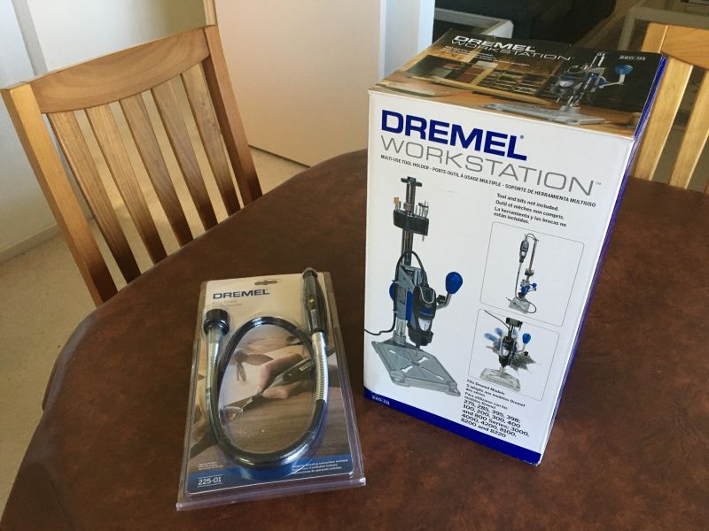
The 3rd party flex tool was cheaper from on-line (China) but delivery time and quality were both uncertain so I opted for the real deal. Instead of a clamp, I went for this rather neat press that also will hold the Dremel when you're using the extension drive. Spoilt myself rotten for once.
Last edit: by Colin W
Posted
Full Member
Longchap : I did have a razor saw of sorts 40 years ago but it always caught on the web so I abandoned it and have used the carborundum disk cutter ever since. Power transfer is a simple flexible cable as there is a limited stroke, just 7 wires, common return and 6 roads (selected by a rotary switch).
Peter : I considered the screw method but the screws are not adjustable once filled with solder and I remembered when I had last used OO I had a supply of copper pins, fortunately steel pins work just as well, this is very close to the baseboard edge so I wanted minimum damage to the wood. I doubt I will ballast the traverser so will just add a few more track pins in time. I used a length of straight wood and had the advantage of new track straight (pun) out of the box.
Terry : I have been engineering one way or another for long enough to make a personal choice :) IMOP compression cutters of any sort cause to much distortion to be tidied up afterwards.
Ron : I like the flexible drive idea but who is going to hold the mini drill while both my hands are holding the track down and the cutting disk ?
Colin : I am glad you like it, the stub roads are for locomotives, so an arriving train is left uncoupled on the traverser and the locomotive on the stub, the traverser then moves to a free road allowing the newly arrived locomotive to move to a similar stub at the other end from where it can be attached to the departure end of another train in the traverser, this can all be accomplished without the "hand of god" reducing wear on transfers and paint on the loco.
Marty : I cut a bit through the rail on each side in turn to avoid to much heat in the rail, I can sense it through my fingers that are very close holding the rails down.
One mistake I have made is to not take enough care measuring out the track ends, I only marked the centre line of the tracks, I should have chosen a rail instead to ensure an accurate pitch, consequentially the table has to be nudged slightly when wishing to use a different pair of tracks in any one position if that makes any sense at all :roll:
Regards
Roger
Roger OO DC Steam
Posted
Full Member
Our posts must have crossed. The drill press which I bought, a handy device in its own right, holds the Dremel for you so you can apply the small portable one. Even so, I think it will be a good plan to have a small jig to fit over track and rails to hold them firm when applying the disk.Ron : I like the flexible drive idea but who is going to hold the mini drill while both my hands are holding the track down and the cutting disk ?
Thanks also for the info regarding the end sections of the unit.
Colin
Posted
Full Member
A flexi-drive is now on my shopping list ……………………presumably it "fits all" because I have 2 mini drill one of which isn't a Dremel and, as the Dremel lives in the press, it will be the "other" which will use the flexi-drive. :thumbs
'Petermac
Posted
Full Member
But Peter you only have to worry if you live in a warm country with sun (about expansion)Even yours Roger, done with a slitting disc, looks very tight on clearance to me …………… :hmm

Roger OO DC Steam
Posted
Full Member
'Petermac
Posted

Site staff
I leave it loose on the layout sitting on tracks - it doesn't move….Ron : I like the flexible drive idea but who is going to hold the mini drill while both my hands are holding the track down and the cutting disk ?
Regards
Roger
Ron
NCE DCC ; 00 scale UK outline.
NCE DCC ; 00 scale UK outline.
Posted

Site staff
[user=6]Petermac[/user] wrote:But Peter you only have to worry if you live in a warm country with sun (about expansion)Even yours Roger, done with a slitting disc, looks very tight on clearance to me …………… :hmm
Expansion ?? I live in Scotland, all I worry about is Rust !
( Always thought I would have been better taking up RC boats :roll:)
Wasnie me, a big boy did it and ran away
"Why did you volunteer ? I didn't Sir, the other three stepped backwards"
"Why did you volunteer ? I didn't Sir, the other three stepped backwards"
Posted
Full Member
I got some points yesterday afternoon :Happy In case anyone like me was wondering what the current state of affairs with Peco re isolation etc (of live frogs) hopefully this picture of large, medium & small radius code 100 underside might help.

The all have the ability to isolate the frog from the blades by cutting the exposed links underneath. To make them DCC friendly the blades need to be linked to the adjacent running line, easy in the top two where the undersides are exposed but on the short radius the sleeper base will have to be cut away in a suitable location.
I use so called DCC friendly wiring to prevent shorts on the traction supply when the frog relay changes at a different time to the mechanical movement of the blades.
Mechanically the throw is 3.3mm and the tie-bar hole diameter 1.4mm.
Roger OO DC Steam
Posted
Full Member
I have had the odd faulty brand new point with missing links in those moulded grooves under the "V" so it's worth checking before nailing them down ……..
In my case, I'd done the necessary soldering, cutting of the midway frog links and fixed them down then wondered why all locos stalled on them. Faulty manufacture was not expected so it took an age to find the problem.
'Petermac
Posted
Full Member
I too make my electrofrogs "DCC friendly" in the same way Roger but have a distinct dislike of micro-switches finding the fiddly to position correctly so use the Gaugemaster DCC 80 to switch frog polarity - a bit pricey maybe but easy to install and thus far, they do the job !
Ohh boy am I having fun with quotes today!! Peter I switch my frogs either from an extra pole on the control panel point operating switch or by a relay controlled by the same method (depends how far away it is)
Thanks for the tip Peter, something to watch for!I have had the odd faulty brand new point with missing links in those moulded grooves under the "V" so it's worth checking before nailing them down ……..
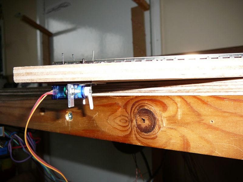
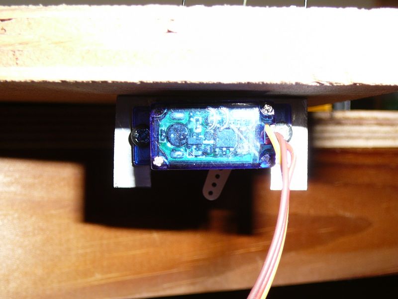
Today having got some points I concentrated on the servo mounts (prototype), bought a 2M length of 20x20mm angle at the local hardware store for just £5 (bet that's cheaper then the DIY superstores) and chopped 40mm off it. A slot was cut in one side and the servo mounted behind it with M2.5 bolts. A small fulcrum hole was drilled in the other side in line with the shaft but sufficiently in front of it for the wire to clear the horn screw, two mounting holes complete the drilling. The wire is 0.55mm dia iron gardening wire attached to the horn with a dogleg. After mounting under the baseboard the wire is pruned flush with the tiebar with the servo in the centre position shown, the tiebar needs to be held central as it tends to spring to one side or the other and you want the wire the right length. Total movement requuired from the servo with a 12mm baseboard in OO gauge is about 60 degrees.
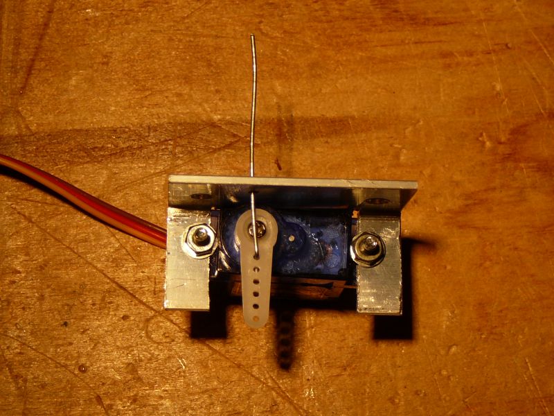
Servo under baseboard, point on top
Point in one position

Point in tother position
Last edit: by fourtytwo
Roger OO DC Steam
Posted

Full Member
My apologies for taking so long to reply to your enquiry regarding the new V1/3 chassis.
The old ones are split but as I am a confirmed DC user cannot comment on the difficulty, or otherwise, of conversion to DCC. The older chassis can be a pain if brushes need replacing but this has not been an issue for me with my two. I bought them both, pre-loved, from eBay - if you know what you are looking at, this is not a problem.
The new version is a "conventional" chassis but the detail is finer and the colouration of the wheel and motion does add to that effect. Like you, I have yet to weather my locomotives so cannot comment on how they will look when covered in the usual layers of grime and brake dust.
My new layout will require these engines to run in either direction with a train of 4 coaches - often the older Bachmann short Thompson types with the grotty bogies. They all performed extremely well on the my old layout so I am not expecting any issues. They also successfully negotiated 2nd radius SetTrack in the storage area and so the new layout will not challenge them - I do not have anything under 24 inch radius.

Above is the SR terminus plan from 1976 showing the similarity with your own (re-drawn by me in AnyRail). The siding top right went to a dairy whilst the curved siding was a headshunt. The loco shed was sited inside the curved main line. I always thought this was a really good, compact design although when operating from the front, the placement of the sidings at the rear, some 36 inches from the front edge, may be seen as problematic. The back siding was marked for coal traffic and the goods shed was sited at the end of the bay.
Barry
Shed dweller, Softie Southerner and Meglomaniac
Posted
Full Member
"Iron gardening wire" - I'm sure I'll know what that is but probably under a different name………. I use piano wire on mine. Do you remove the springs from the points ?
'Petermac
Posted
Full Member
Roger
My apologies for taking so long to reply to your enquiry regarding the new V1/3 chassis.
The old ones are split but as I am a confirmed DC user cannot comment on the difficulty, or otherwise, of conversion to DCC. The older chassis can be a pain if brushes need replacing but this has not been an issue for me with my two. I bought them both, pre-loved, from eBay - if you know what you are looking at, this is not a problem.
The new version is a "conventional" chassis but the detail is finer and the colouration of the wheel and motion does add to that effect. Like you, I have yet to weather my locomotives so cannot comment on how they will look when covered in the usual layers of grime and brake dust.
My new layout will require these engines to run in either direction with a train of 4 coaches - often the older Bachmann short Thompson types with the grotty bogies. They all performed extremely well on the my old layout so I am not expecting any issues. They also successfully negotiated 2nd radius SetTrack in the storage area and so the new layout will not challenge them - I do not have anything under 24 inch radius.
Above is the SR terminus plan from 1976 showing the similarity with your own (re-drawn by me in AnyRail). The siding top right went to a dairy whilst the curved siding was a headshunt. The loco shed was sited inside the curved main line. I always thought this was a really good, compact design although when operating from the front, the placement of the sidings at the rear, some 36 inches from the front edge, may be seen as problematic. The back siding was marked for coal traffic and the goods shed was sited at the end of the bay.
Barry
Hi Barry and thank you for your reply, I only had a brief look inside, looked like a can motor so not even sure how to get at the brushes, hopefully will never need to! Of course DCC conversion doesnt worry me one jot as I shall remain DC :)
Your layout is very interesting, someone mentioned mine had to much track in it but I am thankful I constrained it to a 2ft baseboard width so that all important access to the goods yard at the back is not to much of a problem (till the paunch gets bigger :oops:). The infill industrial in the right hand corner could be anything depending upon what traffic one wants an excuse for :) I probably over developed the MPD relative to the size of the station but I like seeing my loco's in the flesh rather than hidden in storage roads. I love the way your layout flows around the corner almost as if the corner were not there at all many thanks for posting it.
Roger
Roger OO DC Steam
Posted
Full Member
That's a nifty servo mount Roger and I'd guess probably cheaper than the aluminium channel I used initially.
"Iron gardening wire" - I'm sure I'll know what that is but probably under a different name………. I use piano wire on mine. Do you remove the springs from the points ?
Hi Peter, thank you, all I have to do now is reproduce it umpteen times. I just remembered where the wire came from (it was originally brown plastic covered), fortunately I have more then enough for the layout as I have had it so long I have no idea where it came from!
I definitely do not remove the springs from the points, the servo's have plenty of grunt to overcome them, I have read that some people do but have not been able to work out why.
Roger
Last edit: by fourtytwo
Roger OO DC Steam
1 guest and 0 members have just viewed this.