Waddlemarsh
Posted

Full Member
Somewhere SW of London. Somewhen before today
I have yet to make my control panel so I shall be following this keenly…Michael

Posted

Full Member
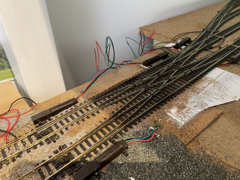
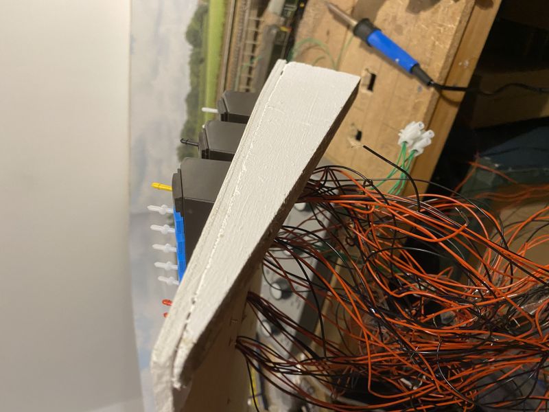
Space here forces me to site the panel on a corner of the actual layout rather than beneath or in front of it. The white board is an offcut of marine ply with triangles of chipboard as its sides which will give it a slight "towards me" angle rather than everything sitting flat on the main board. I have to make a few large holes in the main board for wiring but that will pass through in looms; the small white panel however requires numerous smaller holes as shown above to accept the wiring from each bank of switches and from the main power controller. That will sit in half-depth recesses bored into the ply keeping the controller just above its surface allowing air to circulate beneath it.
I have a week of annual leave booked in early March with which I can do nothing outside owing to the continued presence of this ruddivirus. As full wiring requires a lot of items to be moved out from under the layout - and then returned when the job is done - I hope to take a few days of that week to completely disrupt everything in the room and wire up beneath the boards. Some is already done. Most points were pre-wired when the boards were first built a surprising ten years ago now. All that is needed in most cases is to connect A and B and test that it all works. The lighting will require rather more work and might not be completed just yet.
Posted
Full Member

Posted

Full Member
'Petermac
Posted
Full Member
Ratio item 454 "SR Lamps" which require painting despite the appearance of some shop illustrations.Pin vice with a 0.5mm bit to bore a pilot hole through the shade followed by a 0.8mm to allow two wires to be threaded through. The shades were also slightly bored out with a 5mm bit to accept the LEDs in a recess in prototypical fashion. And a job lot of pre-soldered LEDs from China. You will also need resistors to dim the lighting from "dazzle" to "glow"They look interesting Rick - a little too "modern" for me but where did they come from - maybe they do an older model ……….
I am taking my inspiration from this post which I found through a simple internet search. Note that he says a 0.05mm drill bit. That is much too fine even if such a thing exists. 0.5mm is correct. https://www.newrailwaymodellers.co.uk/Forums/viewtopic.php?t=55782
 Last edit: by Gwiwer
Posted
Full Member
I don't know about being "too modern", Peter. The Southern was producing pre-cast concrete fittings and fixtures from the 1930s onwards.They look interesting Rick - a little too "modern" for me but where did they come from - maybe they do an older model ……….
:hmm
Jeff Lynn,
Amateur layabout, Professional Lurker, Thread hijacker extraordinaire
Amateur layabout, Professional Lurker, Thread hijacker extraordinaire
Posted
Full Member
Newly-arrived Kernow MRC / Revolution Trains Cargowaggon is tested on the tramway-radius corners of Waddlemarsh using an 07 as traction.
These are superb wagons. Well out of my themed era but one was purchased anyway. I am pleased to report it rolls freely through even my tightest curves.

Posted
Full Member
The bridge and backscene look great in that shot. :thumbs
'Petermac
Posted
Full Member
It's a flexi-track curve so not to a fixed radius. End-to-end it is 400mm or about 16 1/2 inches. At the mid-point it is somewhat tighter than that and probably close to the 370mm (15 inch) or so of First Radius fixed-geometry trackWhat radius is that curve Rick ?
The bridge and backscene look great in that shot. :thumbs
Appreciate the comment on the scene; getting that right wasn't easy. I am stuck with joins in the sky for now; I hope they can be eased out with pastels at a later stage but for now they can be dealt with in photo-editing software when it matters.
Posted
Full Member

Posted
Full Member

Posted
Full Member
I cannot solder indoors. The puff of smoke may trigger the alarm. Any spill may harm the carpet.
But there is always modelling space. In this case on the potting bench outside the back door.

Posted
Full Member
:pathead
Cheers,John.B.:thumbs
Posted
Full Member
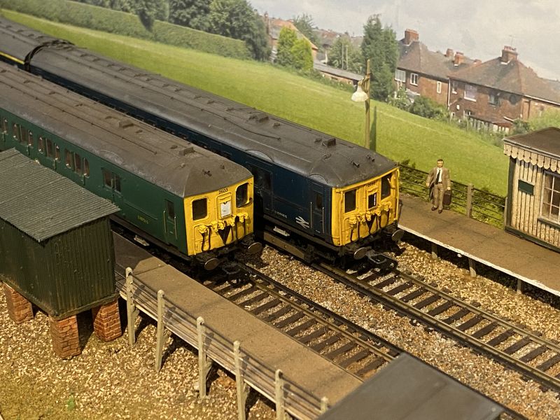
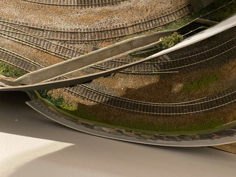
The “off-scene†view through the footbridge requires scenic decoration for some distance. The curve of the track, necessary to accommodate the sharp bend, takes it almost to the edge of the baseboard.
The photographic backscene is therefore curved to match the track and has required a small piece of card to be glued as an outrigger to the baseboard to avoid a gap.
This has now been fitted and the area ballasted / greened so that the view through the bridge appears to be a continuation of the main scene.

Posted
Full Member
Posted

Site staff
Cheers
Matt
Wasnie me, a big boy did it and ran away
"Why did you volunteer ? I didn't Sir, the other three stepped backwards"
"Why did you volunteer ? I didn't Sir, the other three stepped backwards"
Posted
Full Member
Michael
Posted
Full Member
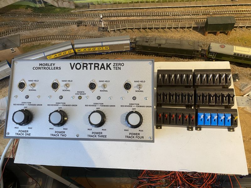
Switch banks now glued and screwed down; controller placed.
I am not happy with the position of the controller. It blocks too much of the view. My thinking is to cut the angled panel such that it only holds the switches and mount the controller flat on the baseboard.
Posted
Full Member
Love the control panel - Morley I hear, are very good and can almost compete with DCC ………………almost ! :lol: :lol:
'Petermac
Posted
Full Member
Someone miswired four of the six switch banks. :oops: I was following the wiring diagram for signals not points

Today the top pair were rewired correctly which was tricky but far from impossible. The levers click inti the cradles but are not fixed so they come back out with a little persuasion.
Tomorrow will see the middle pair rewired. The lower pair are fine - bottom left is for signals anyway and bottom right is on-off switches for isolating sections and those should all be correctly wired.
It’s a hobby, they tell me

1 guest and 0 members have just viewed this.