Waddlemarsh
Posted
Inactive Member
Somewhere SW of London. Somewhen before today
Sorry about the gout.I started getting gout a couple of years ago and can attest to how painful it is.
Evan

Posted

Full Member
In the past few days I have received a pack of resistors and more tiny lights. I shall have to start some electrickery soon. It's not a part of the hobby I look forward to even if the results can sometimes be rather good.
Posted

Full Member
I also think it's very bad timing to have some lights delivered just when you're fit enough to think about going back to work …………………….
Looking forward to seeing them installed. :thumbs
'Petermac
Posted
Full Member
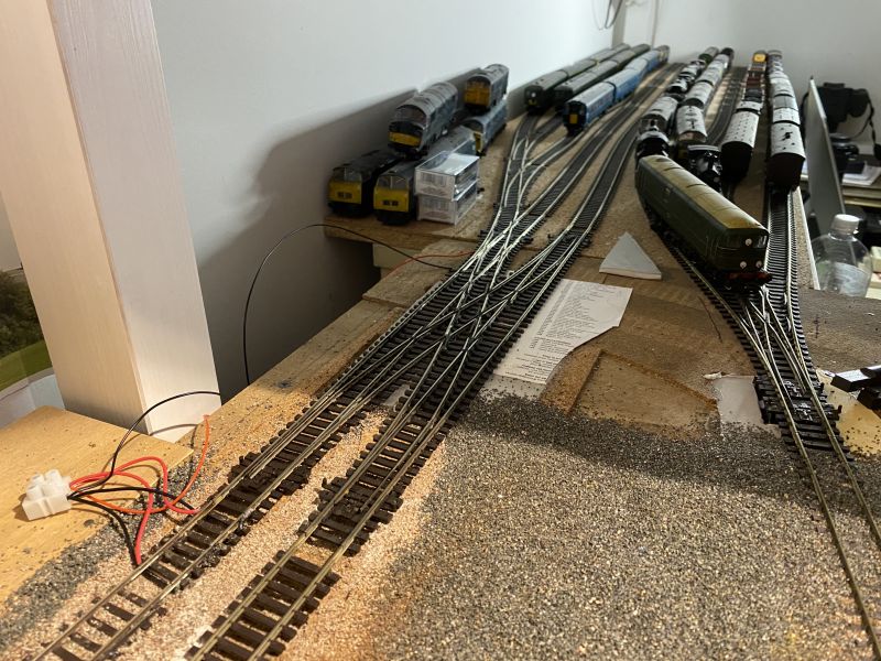
The crossover unit which was giving me endless electrical problems in its electrofrog form has been rebuilt with insulfrog points and crossings. A couple of touches with the soldering iron to power the double-slip and we’re in business.
The temporary set-up of merging the tracks is gone and the intended configuration has returned. And it works as intended. One minor task remains namely to switch the power to the one siding leading straight off the slip. This powers up no matter which way the slip is set but a simple insulated joiner and a push-to-make switch will fix that. I could use an on-off switch but don’t have one handy. I do have a lot of push-to-makes in stock
The wiring will be hidden from view because with this piece of the jigsaw fitted I can now build the last piece of backscene which will obscure the view of the sidings from the camera - but not totally block the operator’s view.
Posted
Full Member
Posted
Full Member
'Petermac
Posted
Full Member
The standard version is four points and a crossing. My custom-built one replaces one point with a double-slip to give maximum flexibility in minimal space. It comes at the cost of slight wiring complications however even in insulfrog form. As one wires the outer curved rails of the double-slip so the power will pass along the sidings no matter which way the blades are set and only be cut by a point farther into the yard being set against the road.Wow that is some price of kit and looks ‘fun’ to power correctly. A very good use to maximise space though.
So a couple of insulated joiners are required and a couple of simple switches. I thought just one but two will be needed because both exits from the double-slip towards sidings require an insulated joiner fitted to prevent powering up when not required.
Just imagine this in electrofrog. I had it built, I tried every which way and suggestion (and with a lot of help from some very knowledgable modellers) but it wouldn't play ball. There were always shorts somewhere and always at least one dead section.
 Last edit: by Gwiwer
Posted
Full Member
Last edit: by Gwiwer
Posted
Full Member
Posted
Full Member
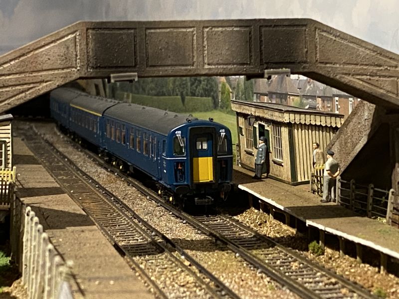
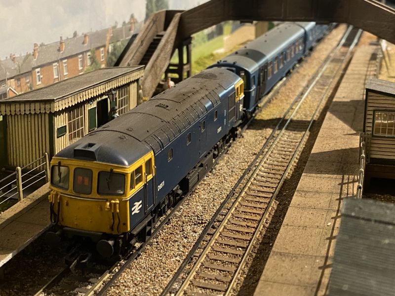
Thank you Chris. I hope there will be many more to come. Any layout will have its natural "sweet spots" for photos - the trick is to fond them if they are not already obvious. Framing the view through the footbridge seems pretty obvious to me and to my mind it also shows the texture and subtle variation in colours I have achieved in what is a scene representing concrete slabs and panels for all its major structures.Two fantastic shots there.
Posted
Full Member
Phil
Posted
Full Member
Posted
Full Member
Cheers,John.B.:thumbs
Posted
Full Member

The scene is extremely realistic - so realistic in fact, that it wouldn't look out of place further north ………. :cheers
Well done Sir.
'Petermac
Posted
Full Member
Some things have to be done. I really must get on with wiring otherwise I'll be snookered when it comes to fitting it all together if I complete all the scenic work first.
Posted

Full Member
Michael
Posted
Full Member
……………………………………… And great to see typical Southern modelled so well - ignore that PeterMac! :lol:
Michael
Regarding soldering Rick - is it wires to rails or other junctions ? I haven't yet found a means of connecting wires to rails without solder but all the other joints have excellent alternatives to solder. I have tried to avoid using solder under the baseboards - I'm too old to scramble about under there and my skin seems to be too delicate to catch the hot drips without it hurting ……………… I'm guessing you don't have access to a garage or shed of some kind - given that Strawberry Hill is in the temperate zone of the UK, you might have some wait for a fine, warm day ……………… :roll: :lol:
'Petermac
Posted
Full Member
Ah soldering.Headmaster wrote:……………………………………… And great to see typical Southern modelled so well - ignore that PeterMac! :lol:
Michael
Regarding soldering Rick - is it wires to rails or other junctions ? I haven't yet found a means of connecting wires to rails without solder but all the other joints have excellent alternatives to solder. I have tried to avoid using solder under the baseboards - I'm too old to scramble about under there and my skin seems to be too delicate to catch the hot drips without it hurting ……………… I'm guessing you don't have access to a garage or shed of some kind - given that Strawberry Hill is in the temperate zone of the UK, you might have some wait for a fine, warm day ……………… :roll: :lol:
Addressing Petermac's question I use the Peco "power joiners" where I can as they come with pre-soldered wires (one red, one black) and are available in Code 75 and Code 100 versions. They sit nicely between the toe-end of points and the plain track beyond but cannot be used on the outer curved rails when wiring a slip-diamond.
The smouldering iron was out today. It's not too warm outside - just 7C - but it has to be an outdoor job. In the afternoon sun it was just warm enough for fingers to work and the job to be tinned.
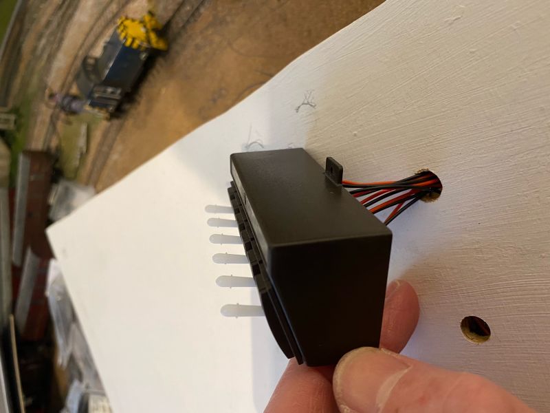
One block of switches has been prepared and now only needs me to scramble beneath the boards (which in turn requires extraction of the numerous crates and boxes stored in that space) to be connected to points and tested.
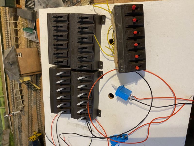
The panel has started to look like it may become a panel! There are a few parts still awaited following last year's Peco shutdown but mostly it's all here and the only delay is me.
Six cradles of switches will be required in all. Four to operate points, one to operate lights and one to manage the various insulated sections. The controller will sit to the left of the switches.
When feeding the wires from the switch cradle through the hole in the panel and towards their eventual destiny beneath the layout each pair of red / black wires was taken in turn and labelled. If left unlabelled how am I to tell which is which when the cradle is fixed in place and I am trying to wire one switch to one point motor?
Regrettably the usual incompatibility between iPhone and Forum has resulted in the images not being displayed correctly. My usual "fix" of rotating then saving them has not fixed it this time either.
Last edit: by Gwiwer
Posted
Full Member
Phil
Posted
Full Member
That’s good. I was on my side taking it!I had to lay on my side to view those :)
1 guest and 0 members have just viewed this.