Teasel Bay
Posted
Full Member
Early construction of a simple 00 garage layout
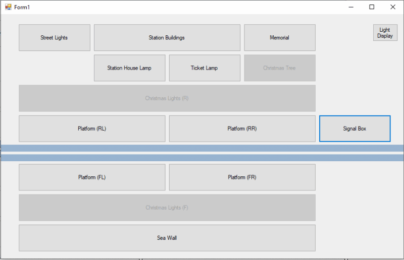
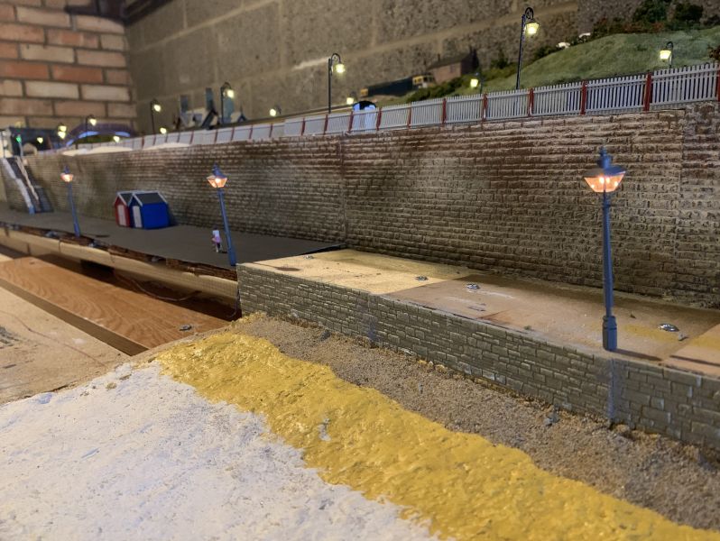
Slow progress over the last few nights, while I planned and setup the lights for the sea wall. As always all my lighting is powered from an Arduino. The Ardunio is now placed behind the sea wall under the layout. The Arudino itself is doing very little, as all it does is provide power to each pin and listen to the USB signal from the laptop which tells whether they should be off/on.
I didn't realise when I bought them that the Gaugemaster lights use lamps rather than LED's, this requires them to be powered by each pin on the Ardunio separately. It does mean when I come to the Christmas display, I can individually turn each light off…. For general use, I've tied them all to a single on/off button. Each button is placed in a retaliative position to the light it controls, it is a functional UI!
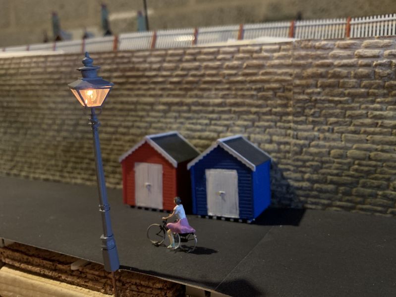
Even though it is going dark, the lady is still exercising on the sea wall….
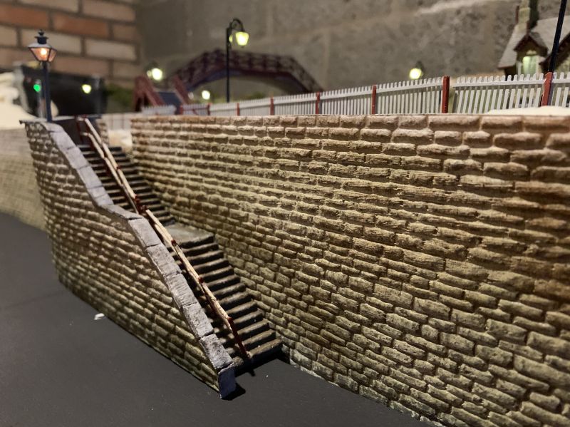
I've placed one on the corner of the steps leading down. I think it finishes them quite nicely (Although I've just noticed I need to tend to the handrail and nudge it back into palace after sitting it sideways to drill, solder!

Posted

Full Member
It looks great Chris - I'm particularly looking forward to seeing that Arduino perform a lift-off - it sure looks like the shuttle flight controls ………………………. :shock: :shock: :shock: :shock:
My system looks far less complicated - a big white 3 inch square switch which gives me a choice of "ON" or "OFF" - the bonus being the "ON" bit has a red background to add some colour.
Does your Arduino do the same ?……………………

'Petermac
Posted
Full Member
I'd image under every layout is at least one dim red light confirming power. You only need two wires with DDC though remember…..My system looks far less complicated - a big white 3 inch square switch which gives me a choice of "ON" or "OFF" - the bonus being the "ON" bit has a red background to add some colour.
Does your Arduino do the same ?……………………
Posted
Full Member
'Petermac
Posted
Full Member

Both the power car and the dummy now have a nice squeal of a Valenta engine.
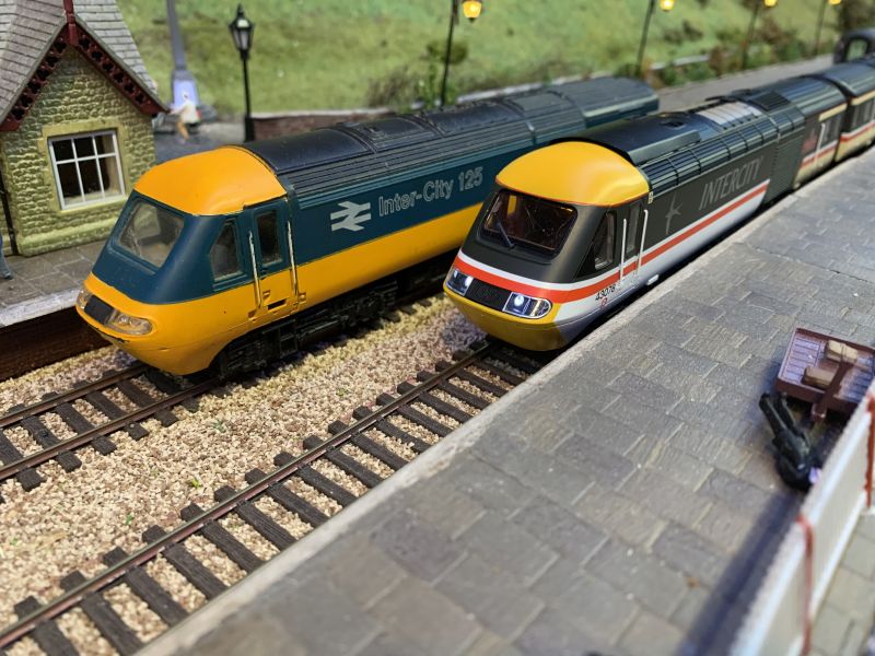
There are a lot of improvements over the 70s model my dad had. One think I didn’t consider is acquiring coaches, they seem hard to get hold of. So far I’ve got the restaurant and two others on the way…

So at the moment I’m running the unusual set of 2 + 1…. suppose you don’t have far to go if your hungry….. oh well, 2 more arriving soon and Hornby releasing a new set at the end of the year, I’ll have a full set one day.
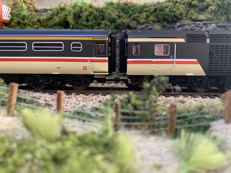
I’ve also upgraded the coupling to use Hunts Coupling. It is a new 3D printed NEM socket fIt magnets. So basically makes my stock compatible with the boys Brio! I’m pretty impressed with them so far.
 Last edit: by TeaselBay
Posted

Full Member
Staying on the thread Kevin.
Posted

Full Member
Ah! Happy memories of Ashford station… my father had been a mechanical engineer there and my uncle and cousin were both train drivers based there….Hi Chris. If my “ Dicky Ticker “ hadn’t got in the way of my plans, I had put my line down for use as a Relief line when the Mainline was closed at Ashford (Kent). Best wishes Kevin
Michael
Posted
Full Member
You might strike it lucky on a well known auction site for coaches, although prices for things seem particularly high at the moment. Although not in the league of purchases such as a leaking tent or a boat with a hole in it, I've seen second hand stock selling for more than brand new. Anyway, the new gift looks super travelling through Teasel Bay.
A quick question, if you don't mind…. What is the advantage of running the lights from an Arduino? I understand that you control it from the laptop - is all of your layout computer controlled? And do the lights get their power from the arduino? Do you still have to use resistors? (And I appreciate that that is actually 4 questions!)
I only ask because I will eventually get around to making my permanent control panel and am considering how I will operate lights…..
Regards
Michael
Posted
Full Member
The trains are controlled with eLink and Railmaster and the lighting through the Arduino on my laptop. I have a touch screen so I can poke away!
In theory one day I want to write my own software to control the trains and take on some automation. I have a proof of concept which I've written which controls the trains I created a thread a while back (http://yourmodelrailway.net/view_topic.php?id=15609&forum_id=32). At the moment though, all my time has been taken on improving the scenery!
My plan is to add some infrared sensors under the track, I have 4 to try out and fire back trains location again using the Ardunio. I can then have route planning and automatic signalling….. I have so many ideas, just no time to implement them! haha…
Posted
Full Member
Michael
Posted
Full Member
So first problem is that both cars were orientated in the same direction, so I attempted to switch cv29 to reverse, but the decoder failed. I have then since learnt that a decoder can’t return a signal without a motor. Does any smart person know why/how that works!?
I then had set the value incorrectly so had lost the lights altogether (I didn’t read the value first). Resetting the decoders did this, but at this point I swapped the locomotive bodies so the lights now worked in the opposite direction to travel….. many resets later I realised my error.
I have now got it to a state where the trailing car is working but the power car’s sounds work in reverse only. So you only get a horn in reverse, which is not ideal.
I now have the number of the guy who writes the sounds to these things and he has just spent an hour looking through and chasing the problem and is emailing me new codes to hopefully fix the issue.
So here is the circles I’ve been following for the last 5 evenings!! How for frustrating….. Hats off to the guy who helped me through my own issues and then the problem with the decoder.
Posted
Full Member
CV31=16 and CV32=3 then set CV369=8, CV385=8 and CV401=8
Simple, aye…
Posted
Full Member
I'd have loved to be a fly on your wall when you were working your way through that - I'll bet there were some words even I don't know …………………… :roll: :roll: :roll:
Did your Guru's reset work ?.
'Petermac
Posted
Full Member
Staying on the thread Kevin.
Posted
Full Member
A sound piece of advice Kevin. The only advantage is that no matter what you do they are easy to reset to factory default. A trick I applied many times above!Hi Chris. I was advised not to bother with CV’s? Maybe that is poor advice, but as long as it goes in the correct direction and stops when I want it to that is good enough for me. Best wishes Kevin
Posted
Full Member
 hmm
hmm Back to the shop to be tested the decoder goes I guess.
Posted

Site staff
Edit - Just re read your posts and I see that its now the powered car that is operating incorrectly. Are both chips under the same Address ?
Wasnie me, a big boy did it and ran away
"Why did you volunteer ? I didn't Sir, the other three stepped backwards"
"Why did you volunteer ? I didn't Sir, the other three stepped backwards"
Posted
Full Member
Cheers Pete.
Posted
Site staff
Regarding setting cv's etc. If you solder a 100 ohm resistor across the motor (orange and grey) wires the decoder thinks it's a motor and will be able to be written to.
Never heard that one before :thumbs. The method I've used is to put both powered and dummy on the programming track, program in the address and cv settings you want on the Dummy, remove the dummy and then program the address and cv settings you want for the powered car. In Ian's case as its pre programmed sound decoders I would have removed the powered car chip, put the dummy car chip in, make cv changes and replace both chips in the relavent cars so removing any chance of beggering up the settings in the powered car
What I dont know in this case is wether the wiring in the dummy car has been reversed ? Which would change things a bit
Wasnie me, a big boy did it and ran away
"Why did you volunteer ? I didn't Sir, the other three stepped backwards"
"Why did you volunteer ? I didn't Sir, the other three stepped backwards"
Posted
Full Member
Great bits of advice there! There is no way I’m soldering inside the engine though! I use the swap approach above.[user=1120]peterm[/user] wrote:Regarding setting cv's etc. If you solder a 100 ohm resistor across the motor (orange and grey) wires the decoder thinks it's a motor and will be able to be written to.
Never heard that one before :thumbs. The method I've used is to put both powered and dummy on the programming track, program in the address and cv settings you want on the Dummy, remove the dummy and then program the address and cv settings you want for the powered car. In Ian's case as its pre programmed sound decoders I would have removed the powered car chip, put the dummy car chip in, make cv changes and replace both chips in the relavent cars so removing any chance of beggering up the settings in the powered car
What I dont know in this case is wether the wiring in the dummy car has been reversed ? Which would change things a bit
The guy who sets the sounds said he did change the horns so they only worked in the correct direction but he thinks he has made a mistake. I’m sure it’ll work perfectly once completed!
1 guest and 0 members have just viewed this.