Teasel Bay
Posted
Full Member
Early construction of a simple 00 garage layout
[user=1801]Passed Driver[/user] wrote:Which bit Kevin? If you mean the lift out section, it’s so I can easily get in out when not playing trains with the BBQ etc!Hi Chris. This looks very interesting, but, being a bit of a thicko, I don’t know what and why you are are doing it. I am certain that you have a clear plan, of the work, but, it has gone over my head. Best wishes Kevin

Posted

Full Member
Staying on the thread Kevin.
Posted
Full Member
Ah they are joiners to allow the rails me meet when the removal section is reattached. Without them I’d fear the rails would not join effectively causing derailments. There have been other many similar examples on here previous.Hi Chris. Thank you for your reply, the rail joiners, do they not join satisfactory? And the bird’s eye view, if you have got one of they red gauges? I am certain that they work well unless you are going to have a regular train services passing in both directions on that bend . Best wishes Kevin
As for the inner track on the birds eye view, that is not fixed down and is simply used to gauge the curves so I don’t go too tight. Some buy the nice metal plates.. but this method is cheaper! Haha
Posted
Full Member
 Last edit: by Passed Driver
Staying on the thread Kevin.
Posted
Full Member
They only guid the rails together, not the boards.Hi Chris. Thank you for your reply. If I am reading this correctly, you don’t trust C and L board (whatever they are called) fittings, where on the other hand I do? I also use the “Station Road “ Heavy duty sprung Toggle catches to hold the boards together. Best wishes Kevin
Posted
Full Member
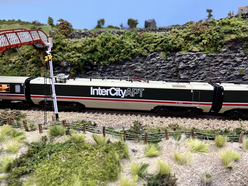
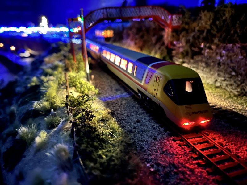
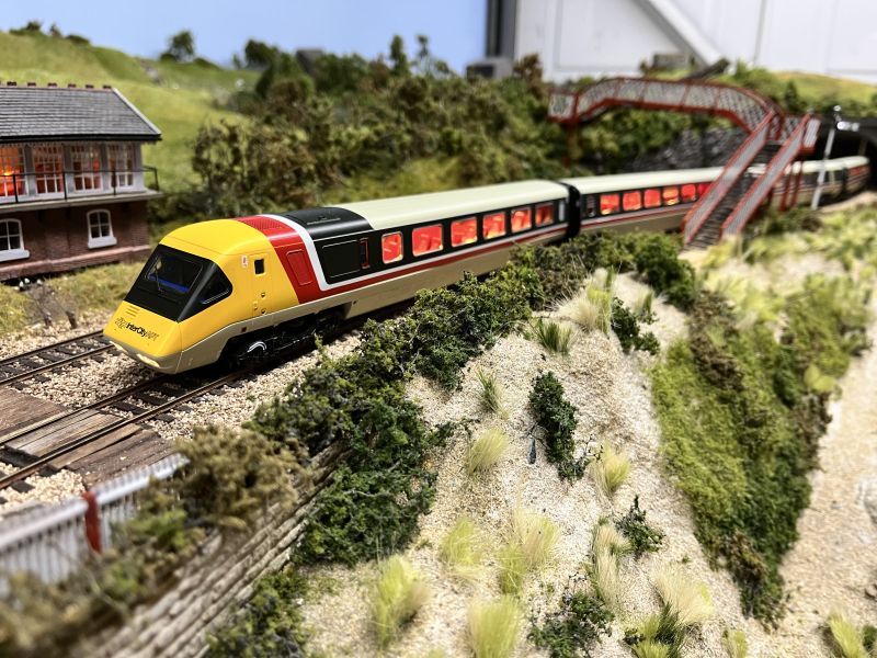
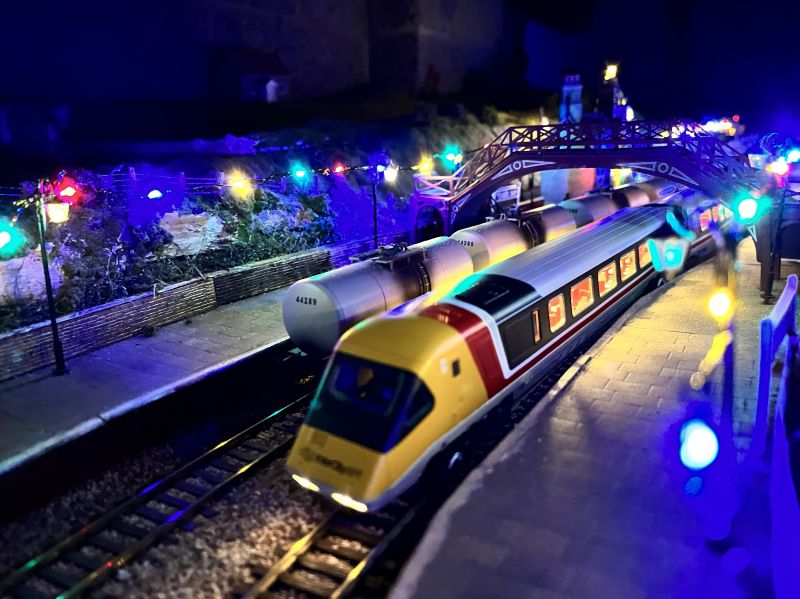
The Hornby APT Set was finally here. A very nice model, with lots of detail. Looks very nice day and night.
I’m very happy with it. It does have a few issues, don’t get me wrong. Even with the capacitors Hornby added the lights still flicker. I have thoughts of adding a wire with a small plug to join the electric bus of every coach, the. It’s all wheel pick up!
Posted
Full Member

Rarely seen view of Teasel due to the lack of scenery, but there will be a lot more happening this end this year!
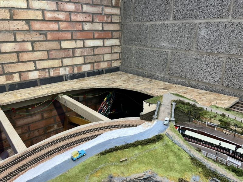
The gap in the middle is going to be a lift out section featuring the 009 railway.
Posted

Full Member
With Wombat Creek out of action for a while, it's great to follow your extensions of Teaselbay.
Cheers,
Claus
www.wct.payne-ellef.dk
www.flickr.com/photos/ellef/
Claus
www.wct.payne-ellef.dk
www.flickr.com/photos/ellef/
Posted
Full Member
Staying on the thread Kevin.
Posted

Full Member
The corner OBS looks a good fit resting on top of Teasel and it will look even better when hoisted to it’s proper elevation. Are you going to test your stock on different gradients before installing the elevated sections?
Good luck and happy modelling.
Best,
Bill
Last edit: by Longchap
At 6'4'', Bill is a tall chap, then again, when horizontal he is rather long and people often used to trip over him! . . . and so a nickname was born :)
Posted
Full Member
Cheers Pete.
Posted
Full Member
I decided after watching many videos and reading stories not to have a gradient between the lower and upper. The lower is the branch, with upper being the mainline, so will have slightly different stock movements. I don’t think in my limited space a gradient would fit nicely.Are you going to test your stock on different gradients
Posted
Full Member
I had a quick Google and it apparently stands for Orientated Strand Board. So I got the acronym slightly wrong there! Hardware stores no longer seem to stock large chipboard boards any more. Does anyone know why!?Yes nicely cut curve in that OBS… what's that stand for?
When I started I did all the cutting and screwing manually! I now have power tools at my disposal, so after a quick measure and run with the jigsaw, I can make easy work of the board!
Posted

Full Member
Just on a point Chris - I think you mean "OSB" rather than "OBS"……………… :roll: :roll: :roll: OSB is "Oriented Strand Board" and is made from thin slivers of wood - almost like wood shavings - laid in different directions and resin bonded to make an extremely strong and hard board. "OBS" I think might be closer to a German Army rank - Obersturmbannfuhrer - often abbreviated to "Oberst" ……………

It's always interesting to see "back stage" views and I'm impressed that the brilliant photos we see appear to take up such a small part of your available space.
Don't you find OSB difficult to work with, particularly when it come to cutting and pin pushing. It's a very hard board. :hmm
'Petermac
Posted
Full Member
'Petermac
Posted
Full Member
No worries! Haha. It was an interesting response nevertheless!Hmm - sorry for my last post, I hadn't read right to the end - I see you've already twigged on the OSB …………………. :oops:
Posted
Full Member
“We apologise for the delay. This is due to the wrong type of wood on the lineâ€.I think this answers your question Kevin : Less train movement this evening as rather large slabs of OBS sit on the tracks after a delivery from Wicks.
Posted
Full Member
I alway try to get in low and try to avoid areas which are yet to look pretty! The garage is a standard single car jobby. I’ve had to be conscious of that since I started at Teasel and as best as I could plan around it.
It's always interesting to see "back stage" views and I'm impressed that the brilliant photos we see appear to take up such a small part of your available space.
Don't you find OSB difficult to work with, particularly when it come to cutting and pin pushing. It's a very hard board. :hmm
As for the OBS, the prototype 009 pins went in fine, time will tell how it reacts. As I said, chipboard doesn’t seem to be available like it used to be!
Posted
Full Member
As I do with all locos on Teasel, I install a stay alive decoder to greatly improve running. The APT is slightly more complex than others as the motor etc sits in a harness which swings when the train curves to allow the tilt motion. So anything added will have to avoid the sides.
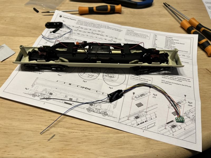
The decoder of choice is the Laisdcc 4 function decoder. Hornby provided a nice space for the decoder, with two screws allowing for it to be fitted which is nice and simple compared to older models where the decoder connection is hidden deep inside. They didn’t however provide space for the stay alive.
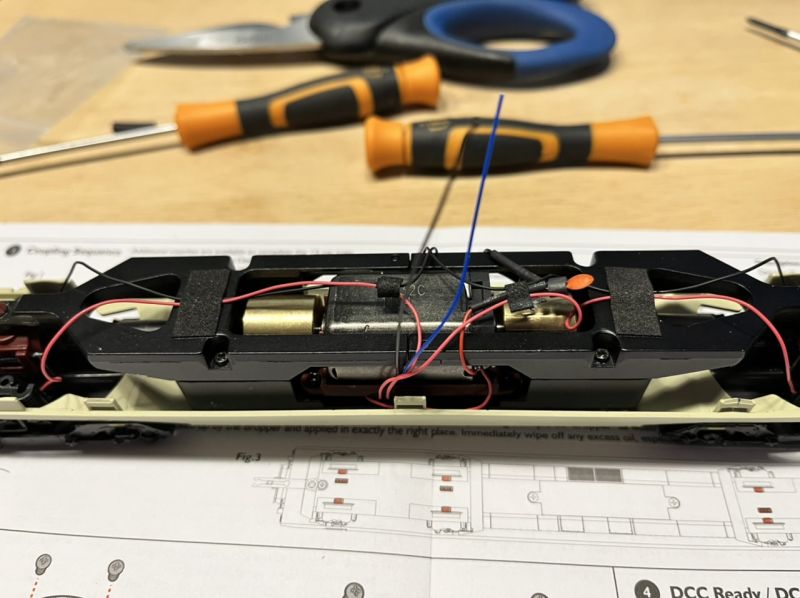
I threaded the wires to the stay alive through the same hole as the pickups beside the motor casing. The capacitor solders on and then tapped to the frame.
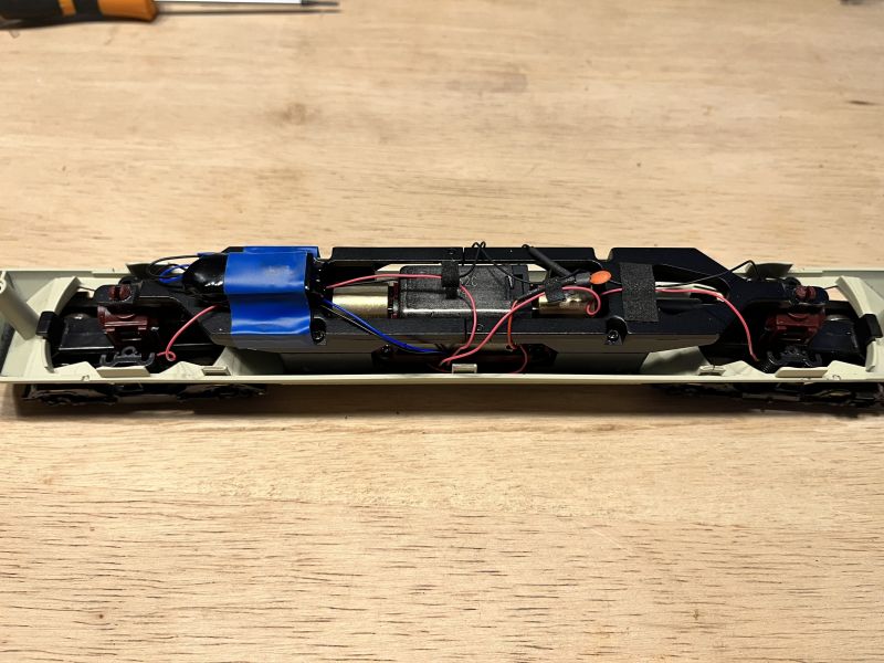
Now… I just have to remember how to put it all back together! :hmm
Posted
Full Member
[yt]fttfwIlUmkM[/yt]
1 guest and 0 members have just viewed this.