OO Gauge - Latton Fields
Posted

Inactive Member
Branch Line - Roundy, roundy with some shunting
I agree with Max,A little beauty
:cheers Gormo
 Last edit: by spurno
"Anyone who claims to have never made a mistake, never made anything!!"
https://sites.google.com/site/greatchesterfordmodelrailway/home
https://sites.google.com/site/greatchesterfordmodelrailway/home

Posted

Full Member
Don't worry about the ding in the embankment. Once all the station work is done you give it another dab of paint, some scatter and a shrubbery… with a path down the middle…. Maybe with a split level effect… Sorry, bit too much Monty Python. It'll be fine.
I've repainted my facia twice 'cause of inadvertent drips of glue and paint.
I also agree that less is more on that corner.
Looking good.
Marty
Posted

Site staff
The problem was only when pushing trucks thought point work and I originally thought was something to do with the insulfrog points at the junction with the goods shed at the end of the platforms.
However, I got the same derailment issues when pushing trucks through the brand new electrofrogs in the other goods yard area.
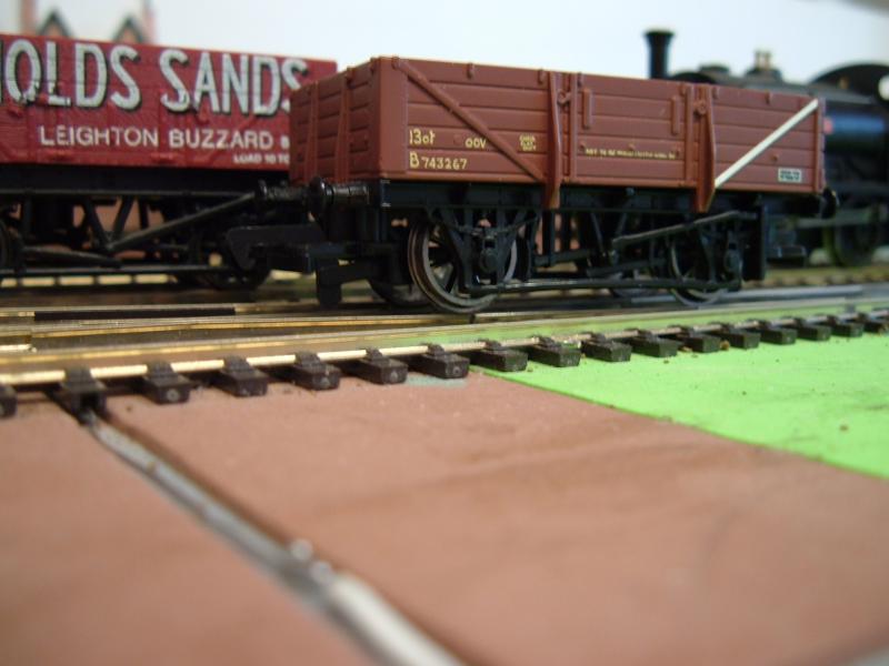

The trucks have brand new Hornby replacement wheels, which turned out to have the back to back set at 14.1mm.
I also found the the joint between the closure rail and the switch rail wasn't that smooth resulting in a bit of a bump, even though these are brand new Peco points.
I don't think it's anything I did when I laid the points, but bending the closure rail a bit and resetting the wheel back to back to 14.5mm cured the problem.
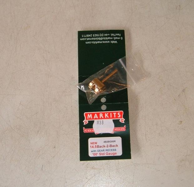
I also bought one of these, which I've been meaning to do for ages.
Some trucks have older Hornby metal wheels which although not the old pizza cutter type, do have a slightly larger flange and front to back dimension, so they are fine at 14.1mm for the back to back.
Appears this is very much a measuring task by individual truck depending on wheels fitted and individual points.
So back to the insulfrogs at the end of the platforms which were now ok, apart from one.
The switch rail doesn't quite meet the stock rail, due to play in the wire in tube point control. I suspect the wire has stretched slightly in use :thud
Ed
Posted
Guest user
Fun and games Ed. I'm having the same issues myself. I'll need to send away for the back to back gauge myself. funny how you regret buying so many wagons, I'll be there for months with them.:thud
good luck with your rolling stock.
cheers
toto
Posted

Banned
Cheers, Gary.
Posted
Full Member
Came as a bit of a shock to me to find out that it doesn't work that way and that I was going to have to learn to get down to track level and pick up the ganger's trade!
Luckily it's fun and there is a sense of satisfaction getting it to work….
The other thing I'm learning is that once fixed it might not stay fixed over time. Especially with timber frames and temperature and humidity variations… who'd a thunk!
glad you got it sorted Ed….
Posted
Site staff
I was using a digital vernier Toto and gently easing the wheels out. Fine for the odd wagon, but then you get a set of stiffer wheels and when you ease them out it goes to 15.1mm. So you gently squeeze them back together and it becomes 13.9mm. Grrrrrr :sad:
Fun and games Ed. I'm having the same issues myself. I'll need to send away for the back to back gauge myself. funny how you regret buying so many wagons, I'll be there for months with them.:thud
good luck with your rolling stock.
cheers
toto
Got mine here, about half the price of the equivalent from that large Liverpool retailer.
http://www.ebay.co.uk/itm/Markits-M38-4B2BgOOR-Back-To-Back-OO-Gauge-14-5mm-With-Gear-Recess-/321647020134?
The wire in tube is GEM Mercontrol Gary. I omitted the recommended Omega Wires due to space constraints, thinking on a shortish run I'd get away with it.
I didn't :thud
Certainly a sense of satisfaction with the wagons Marty along with finally getting the J72 chipped.
However it seems no sooner I fix one or more problems, another 'opportunity' arises.
The point which doesn't close fully now (except with an additional tug on the wire where it meets the lever) and the crossover adjoining it, are three of the insulfrog points I had to adjust by digging out the insulated rail joiner and soldering across the rail joins earlier this year, to avoid stalling issues on some locos.
Then I had the problem of some other locos causing a short which I fixed with the old nail varnish trick. Of course totally forgot about the nail varnish when cleaning the track recently, caused a short and had to reapply it.
I have three more spare insulfrogs which I might use to replace these current ones, to tidy the whole thing up and hopefully make it all more reliable. But since I can't do any more ballasting, finish the platforms or start filling in the ground surface of the goods yard to raise it to rail level until I've decided, I'm just taking a brake to study all the options.
Ed
Posted
Guest user
Thanks for the link for the gauge. Just ordered one up.
Cheers
Toto
Posted
Inactive Member
The wire in tube method is good as long as it is a straight run from end to end. Once you introduce a curve or bend into the line, the wire moves inside the tube. The wire in effect cuts across the corner inside the tube. The result is that you need more throw at the point lever to take up the slack because the wire has to travel slightly more inside the tube.
I`m not sure what you have in place there at the problem point, but it could be just a case of adjustment.??
On the other hand, if you do have a curve in the wire and tube, a return spring fitted to the opposite side of the point tie bar may take up the slack. Think push bike brake set up…..it`s exactly the same problem. The spring in the calliper brake maintains the tension on the brake cable and therefore there is no slack in the line when the brake lever is applied.
I am thinking of using bike cables myself at some point further down the development track and I will have to use return springs to make it work properly.
After all that blah, blah, blah your issue may be just that simple adjustment mentioned above…..:hmm
:cheers Gormo
Edit…..thinking about it???……a spring will only work if the point lever is latching or stiff enough to hold the spring!!
Last edit: by spurno
"Anyone who claims to have never made a mistake, never made anything!!"
https://sites.google.com/site/greatchesterfordmodelrailway/home
https://sites.google.com/site/greatchesterfordmodelrailway/home
Posted
Site staff
I've got straight runs using florists wire to slide switches for the Potters Yard points which are all near the front of the baseboard. No problems.
Latton fields is behind it with longer runs of wire in tube, but none of the curves are exceptionally tight when reading on that other forum that curves of 50mm radius are workable.
I've also read that a 'Z' shaped piece of wire is better at picking up slack than an Omega Loop.
The spring already in the Peco points also helps to ensure the point has switched properly, but only if it's working.
I'm sure a bit of adjustment would fix the point throw, but I also think it's an opportunity to improve running over this section of the layout.
It's annoying that is you have insulated rail joiners on the 'v' rails of each insulfrog point there is a tendency for stalling, and if you don't there is the possibility of shorting.
I could replace the three points with electrofrogs and switch the frogs, but I'd have to buy three new points.
I already have three spare 'newer looking' insulfrog points, but do I install with IRJs.
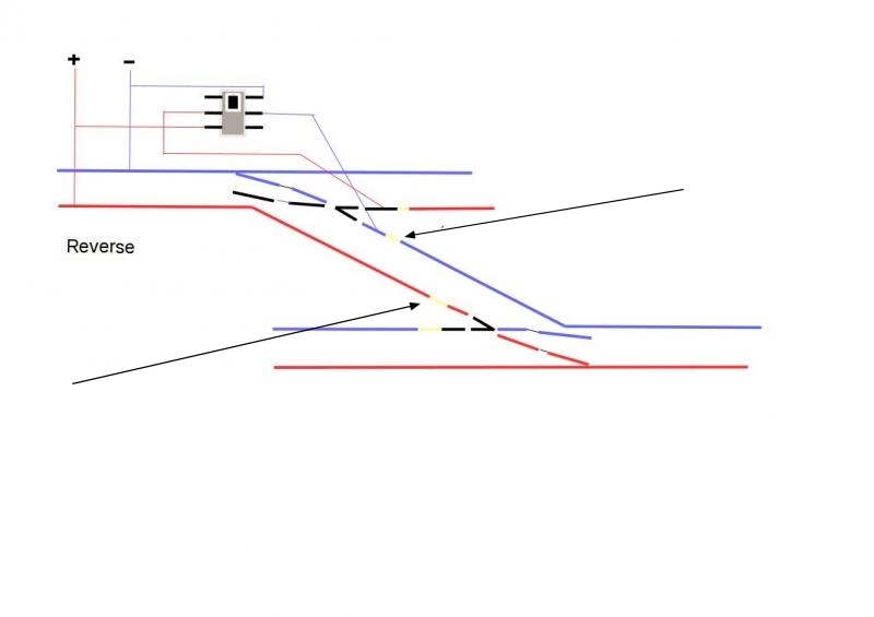
I'm investigating replacing the GEM point levers with slide switches to allow some sort of electrical switching, but still using the currently installed GEM wires. It should allow me to install the replacement insulfrogs with IRJs on the 'V' to stop shorts and only apply power to the relevant switch rail, thereby reducing the dependency of contact between the switch and stock rails for conductivity.
Bit like this quick drawing.
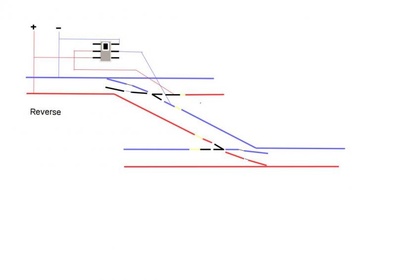
Black sections are frogs and dead bits of rail, yellow bits (if you can see them) are IRJs.
Ed
Edit I should have added, top point uses switch to ensure connectivity and the bottom point is relying on contact between switch and stock rails.
Last edit: by Ed
Posted
Inactive Member
I may be wrong or missing something here, but if you are using insulfrogs, surely all you need IRJ`s for is the connection between the two points ( see the black arrows ), thereby separating the two circuits. The other IRJ`s would be just creating dead spots.
Correct me if I`m wrong, but your circuit seems to be set up for live frog running.
:cheers Gormo
Last edit: by spurno
"Anyone who claims to have never made a mistake, never made anything!!"
https://sites.google.com/site/greatchesterfordmodelrailway/home
https://sites.google.com/site/greatchesterfordmodelrailway/home
Posted
Site staff
Except on live frog you also cut the links between the switch and closure rails to give a totally isolated frog which is then powered from a switch to the correct polarity.
On insulfrog your isolating the rails leading from the plastic 'V', as where they enter the plastic part and are very close together, they could (can) be bridged by a wheel.
On DC it's not a problem and although you may see an occasional spark as a loco crosses the points it's not enough of a short to trip a DC controller.
DCC command stations are far more sensative.
Ed
Posted
Site staff
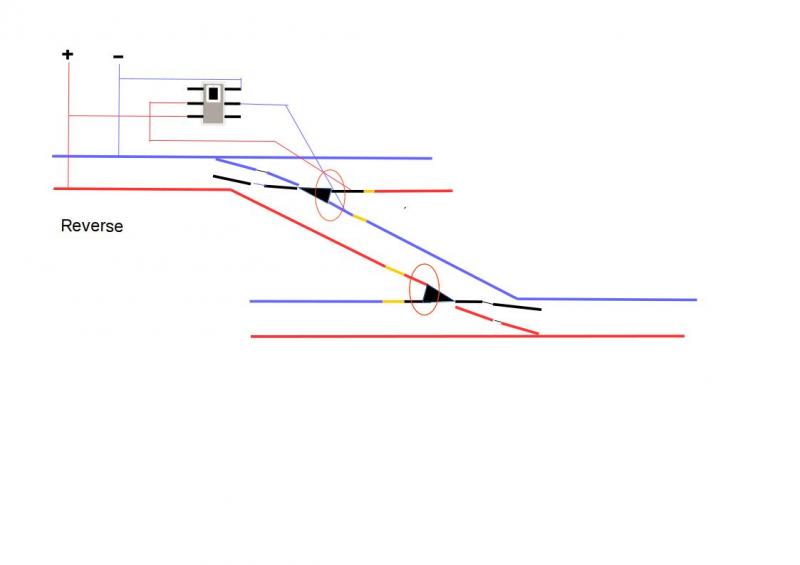
Black triangles are the plastic bits and the red circles indicate where the rails meet the plastic and there can be a short without IRJs.
Obviously not to any scale

Last edit: by Ed
Posted
Inactive Member
:cheers Gormo
Last edit: by spurno
"Anyone who claims to have never made a mistake, never made anything!!"
https://sites.google.com/site/greatchesterfordmodelrailway/home
https://sites.google.com/site/greatchesterfordmodelrailway/home
Posted

Site staff
1. paint the frog tip about 6mm with a clear vanish , nail or supa glue to extend the insulation bit or
2. feed the section via a globe like this http://www.members.optusnet.com.au/nswmn/1156.htm
With Electrofogs, the main reason why the links are cut in the blade/frog rails is so any back to backs of wheels that are under gauge, do not create other short circuits. Once the links are cut, then it is the normal practice to electrically bond the adjacent stock rail to the blade so the system does not rely on blade/stock rail contact.
Ron
NCE DCC ; 00 scale UK outline.
NCE DCC ; 00 scale UK outline.
Posted
Site staff
I believe car brake/tail light bulbs have been used here in the same way as a globe in your link and although that may stop the command station cutting out, it won't actually fix a short.
I suppose the only real solution is to use electrofrog points and switch the frog.
Whether I swap the insulfrogs for electrofogs or just put in newer insulfrogs with additional wiring, I need to somehow get the point operation to include switches.
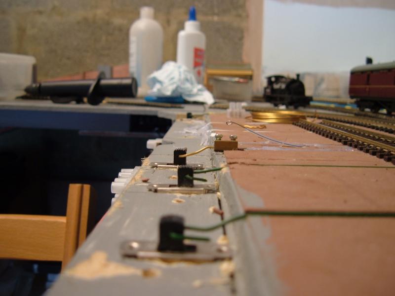
I've tested on one of the crossover points at the other end of the platforms by removing the GEM lever and installing a slide switch, but then got stuck as to how to connect the GEM mercontrol wire to the slide switch.
Sitting in front of the TV watching Great Continental Railway Journeys yesterday evening, I suddenly had a eureka moment.
Use the inner bit from a choc block, the same way Gormo does for his wire in tube systems.
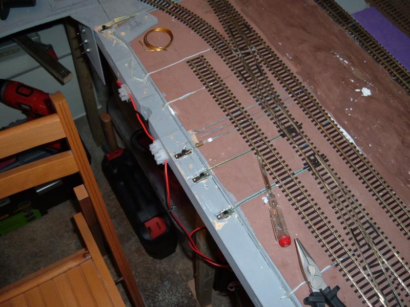
(Ignore the white cable clip, it's just where I was investigating different ways of fixing the wire to the baseboard.)
Needs tidying up, but works ok.
This should also cure any problems with GEM mercontrol wires stretching, as adjustment can be made at the choc block inner.
That was my last spare slide switch but now I know it works in principal, I've just ordered some more.
Ed
Posted
Inactive Member
Those little choc block inners are handy little suckers when you need to join something.
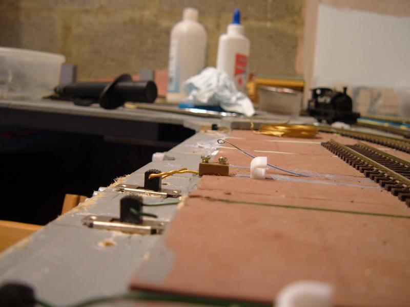
If you need to add any further switching to each point set up, a micro switch laying on it`s side next to and activated by the choc block inner, will give you a SPDT in addition to your slide switch….OR….the micro switch can activate a relay???
http://www.ebay.com.au/itm/10-Pcs-Mini-Micro-Limit-Switch-Roller-Lever-Arm-SPDT-Snap-Action-LOT-WS-/321773120347?hash=item4aeb2c2b5b
:cheers Gormo
Last edit: by spurno
"Anyone who claims to have never made a mistake, never made anything!!"
https://sites.google.com/site/greatchesterfordmodelrailway/home
https://sites.google.com/site/greatchesterfordmodelrailway/home
Posted
Site staff
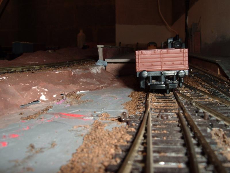
But I have tidied up the first one, in between the monsoon type showers we had yesterday.
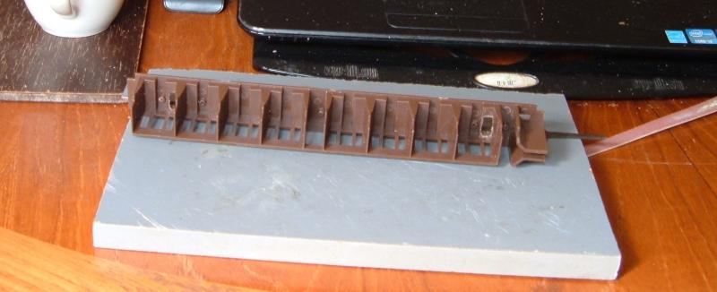
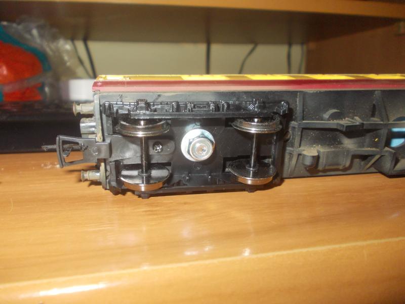
So while waiting for some more switches, I took a hatchet to one of my Hachette coaches.
I been using this to make up a rake of three and I got really fed up with it occasionally derailing.
Although it has metal wheels the back to back isn't easily changeable, and the axles are short compared with Hornby and Bachmann so the holes need to be reamed out to take their replacements.
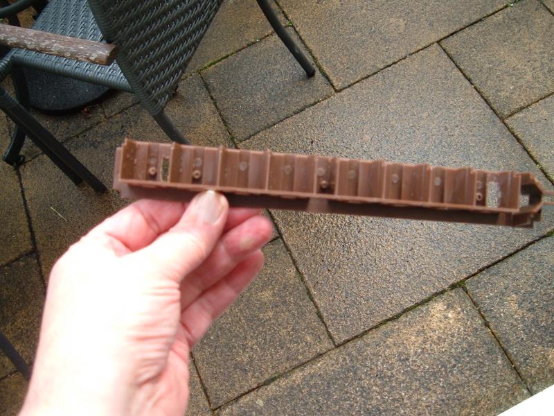
I had some Bachmann Mk1 bogies that I had replaced on an old Triang Mk1 restaurant car and since I wasn't going to use it, I've taken them of and put them on the Hachette.


Had to cut/file holes in the interior though, to allow for the bolts holding the Bachmann bogies.
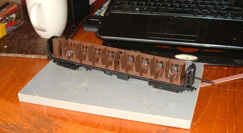
Just got to get the body back on.
Ed
Posted
Banned
I have done exactly the same with my old Triang Hornby Mk1 and Bachmann bogies. It certainly makes a huge difference with how they roll. The only difference between your job and mine is that I put the nut underneath in the bogie.
Cheers, Gary.
Posted
Site staff
With the bolt head below the coach and the shaft stuck up into the interior, they are not really noticeable with all the seats around them.
Ed
1 guest and 0 members have just viewed this.