OO Gauge - Bidley Terminus
Posted

Inactive Member
BR Green Diesel - Computer Control
Not much layout progress in the last couple of weeks.I'm still being distracted by my 110 DMU exercise. I decided to go the whole hog and install directional lighting as well as carriage lighting. Very fiddly and time consuming but I'm slowly getting there. I've been taking pictures as I go and will post them and a bit of description in a separate thread when time permits.
Peter

Posted
Inactive Member
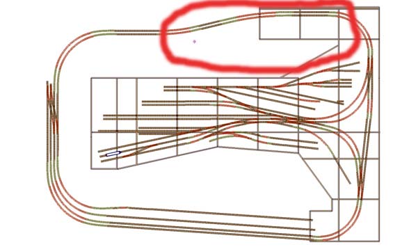
The Y junction to the round the room tail chaser ( on the right hand side of my layout plan (below) has always been a worry to me. As the wiring is now more or less complete and it's time to go back to more scenic creativity, I think it's time to camouflage that issue and also develop a proper plan of how I'm going to give my terminus station a more urban setting.
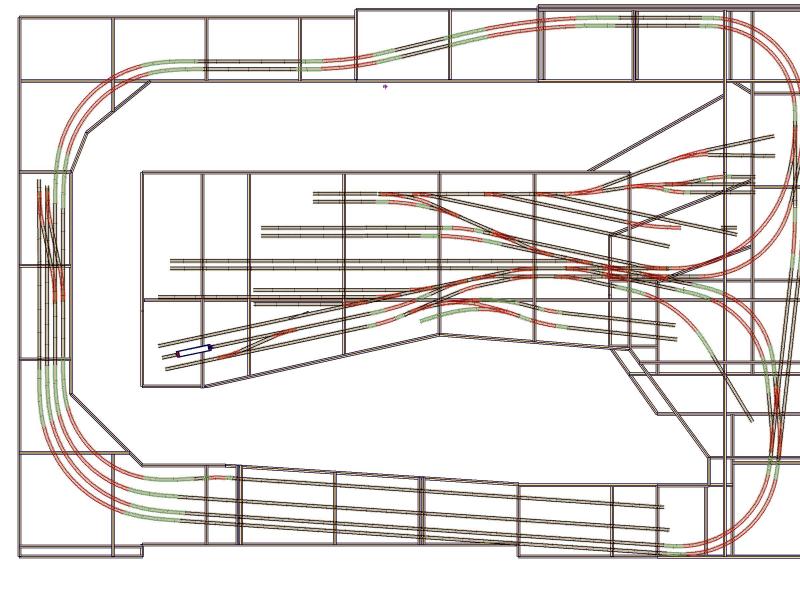
I know some people quickly knock up sketch models in card to work out what looks best, but I can't do that very quickly. Howver I can knock up models in the computer quite fast, so before I reach for the glue and the card I'm going to make a virtual model of my layout using google sketchup. (One of my favourite doodling programs.)
First step was to knock out a quick sketch of the base boards and paste on the track layout. It's not deadly accurate, but good enough for a start.
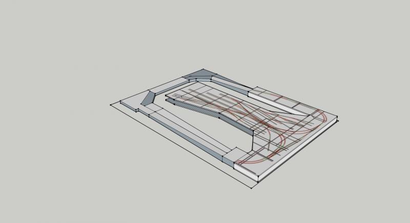
My worrying Y junction is going to be hidden away under the town. I'm thinking I'll build the town on foam board removable modules, so that I can lift them up for maintainance, or to reach a derailed train (god forbid). I've modelled in the rough base of these in the above sketch.
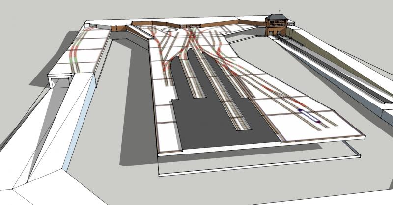
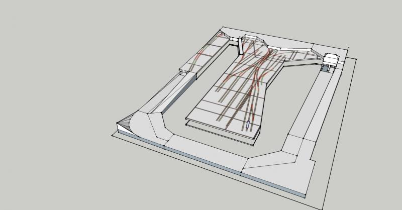
Also now added the platforms for the terminus and Lower Bidley station (RH side). Also added a quick sketch of the Lower Bidley station building. Entry is from above to the platforms below. I thought I should sketch this in because I've already half built it in Card. All other buildings are still a blank canvas.
Hopefully over the next couple of weeks I'll complete the "virtual" layout. I'll post updates here as I go.
Peter
Posted
Inactive Member
Posted

Legacy Member
Posted

Full Member
Thats a great idea using Google sketch up…….wish I had thought of something like that.
I am another RR&Co enthusiast……I would be interested to hear how you operate the layout……is the plan to be fully automated……timetabled schedules …..or?
Regards from Vancouver
Posted
Inactive Member
I intend to operate it via a timetable. I started to create one and a couple of days later nearly fell off my chair when I accidentally and unknowingly started the fast clock and the sound of a diesel horn blasted out of my speakers. I'd programmed a horn action as the first action in my first schedule. I've put some ambient station noise in front of that now to give me a bit of warning and avoid heart attacks.
Having satisfied myself that I have got the theory sorted, I'm focusing now on physical layout building before returning to the software side of things. Can't resist though sometimes just starting a few schedules to watch RR & Co work its magic.
Peter
 Last edit: by Wizmacnz
Posted
Inactive Member
The Christmas holidays has seen me return to the layout with enthusiasm; focusing on scenery and signals. As the signals is all wiring and PCB's and not very interesting to look at,so here is what I have been doing scenery wise.
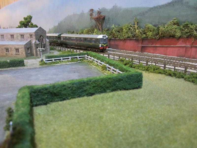
I decided to finish off the piece of layout between my field of cows and where the main line goes under the town.
This is a picture of the area I've been working on…(before)

And this is where it is on the upper track plan.
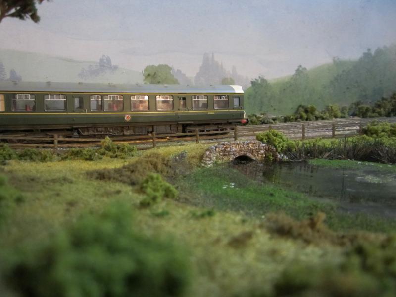
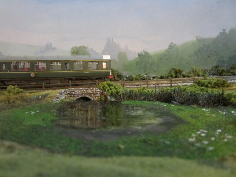
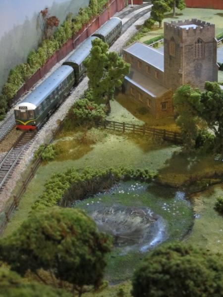
I wanted to include a small pond, the Metcalfe church I made some years back and have a go at some trees. So armed with some two pot epoxy resin, some DAS modelling clay, some cheapo chinese acrylic paints and a selection of woodland scenics gubbins, this is what I came up with. Oh, I also along the way made a home made static grass applicator out of a fly zapper.
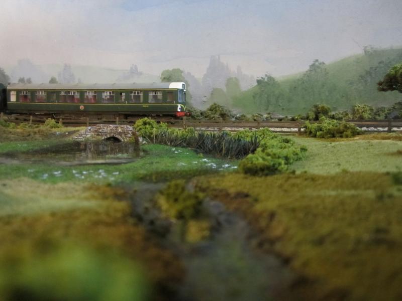
Here is an overview of the area as it looked a couple of days ago.
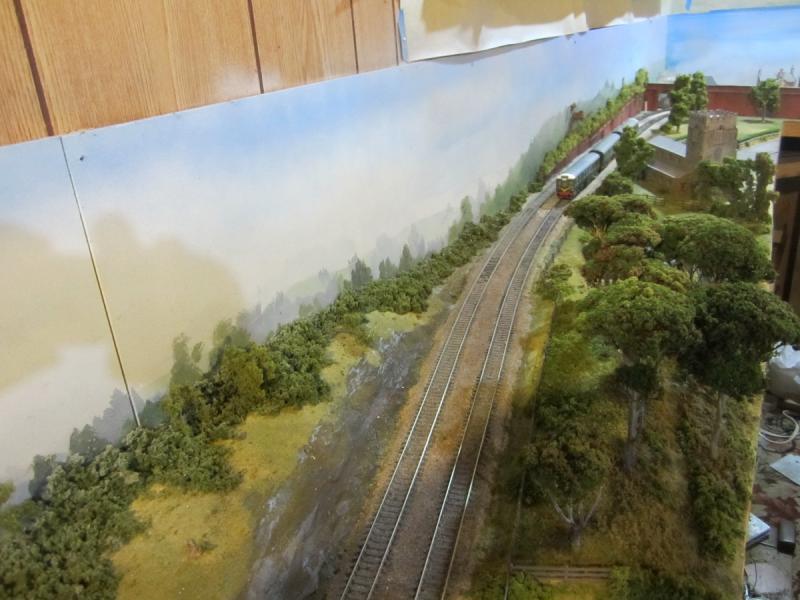
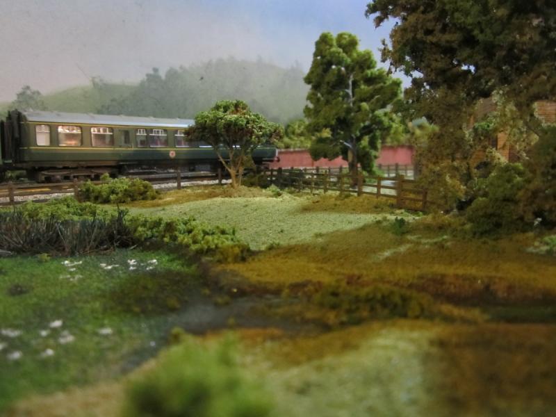
This is the woodlands between the cow field and the pond.

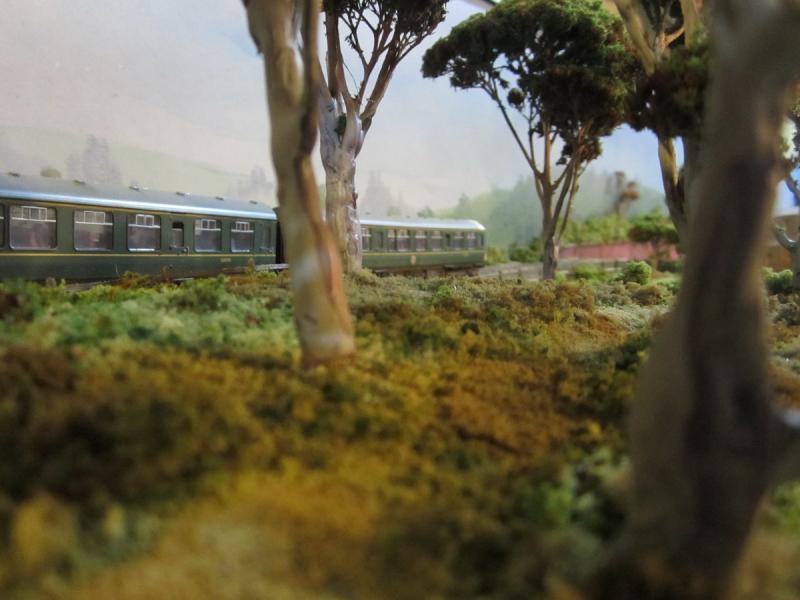
Woodlands again closer to the pond
The pond was an adventure. The first version didn't set in the middle. I used PVA glue, but it was too deep for it to dry in the middle. (well I wanted it dry in my life time.) The second version with two pot epoxy generated so much heat as it hardened that it destroyed the painted plaster shell beneath it. It also seemed to react with the PVA residue, leaving the perimeter tacky for days. The upside was that the lillies and weeds etc attached themselves nicely to the resin.
The culvert was a woodland scenics chopped down to fit. The water lillies are just little tiny dabs of white paint.
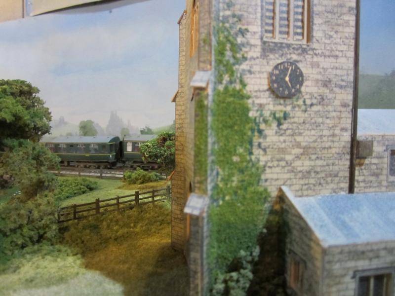
The metcalfe church was something I made some time ago. It will do until I feel the need to build better. I thickened the tower parapets with DAS clay and painted it, to try and make it look less cardboardy.
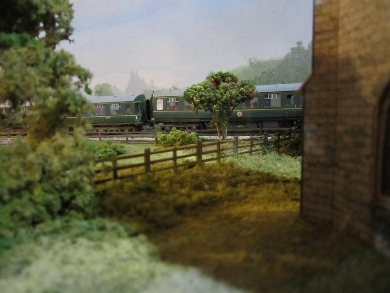
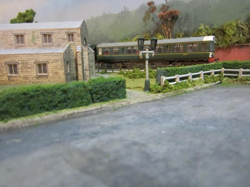
The field between the church and the town is going to have a graveyard when I find the tombstones I bought a few years ago. This are is still to have the weeds and untidiness added. The hedge is painted pot scourer.
One of the things I have learnt is that you should allow more than 20mm between rail and backscene. I'm really struggling to make the retaining wall in to the under the town tunnel look believable.
Final overview picture… then some pictures of signalling ribbon cabling,
Just kidding about the cabling pictures.. but it is going rather well, but with very little visible to show for the effort.
Peter
Last edit: by Wizmacnz
Posted
Full Member
Always try to look on the bright side of life!
Barney
Barney
Posted
Inactive Member
Your talent,s stretch way beyond wireing and computer control.
Thanks for shareing,
Derek.
Last edit: by shunter1
Posted

Full Member
That looks great. I like the painted pot scourer hedge, I dip mine into a 50/50 water/PVA mix and then dip it into green scatter, but I get carried away and it ends up more like an over grown hedge row with trees growing in it, the sort you find between fields in high rainfall areas.
I'll try paint next time.
Lovely pond too.
Carry on.
Marty
Last edit: by Marty
Posted
Full Member
Bob
Posted
Full Member
Hi John
I intend to operate it via a timetable. I started to create one and a couple of days later nearly fell off my chair when I accidentally and unknowingly started the fast clock and the sound of a diesel horn blasted out of my speakers. I'd programmed a horn action as the first action in my first schedule. I've put some ambient station noise in front of that now to give me a bit of warning and avoid heart attacks.
Having satisfied myself that I have got the theory sorted, I'm focusing now on physical layout building before returning to the software side of things. Can't resist though sometimes just starting a few schedules to watch RR & Co work its magic.
Peter
Hi Peter
While admiring the pictures in your latest post, I realised I had not replied to your post of last June:oops: ……do forgive me! I can only plead holidays and absentmindedness!
I am working away at timetables and I, too, experience that moment of consternation when a loco unexpectedly moves off in response to the fast clock advancing faster than anticipated:twisted:.
I dont know about you, but I find there are so many options to explore with RR&Co it is very difficult to adhere rigidly to KISS……….although I tend to think without that one can get sidetracked.
Back to your layout………….great progress with the scenery…..you must be very pleased……those shots with the DMU passing by the pond and woodland are quite stunning
Regards from a damp but mild Vancouver
Posted
Inactive Member
Marty… I do stick a bit of scatter on the painted pot scourer. I just use a bit of undiluted PVA dabbed on. The pot scourers have the manufacturers names printed on the back which isn't totally obscured by the paint, so I beef up the scatter there to obscure it.
Bob … My real interest is the computer control and operation, but I wanted to create an impressionistic setting for the trains to run in without focusing on absolute accuracy. The spray painted back grounds were very quick to do. The junction wiring was relatively straight forward, with an electronic gizmo handling the reverse loop. I just set the route and the electronics handles the polarity issues. My older rolling stock doesn't handle the trackwork as well as the newer stuff.
John … no apologies needed. Your comments on RR & Co and KISS are sound advice. I also wish I wasn't too lazy to properly document what I've done. I try to give schedules meaningful names so that I'll remember what they do, but often find myself deleting schedules with names like P1, because I just can't remember what they were for. I also disconnected some ribbon cables from a tower controller yesterday and afterwards thought.. I really should have labelled those cables before unplugging them. I'm hoping I'll be able to work it out from RR& Co, but can see myself running something slowly around the track and watching to see what LED's light up on the detector boards…..Should have written it down and labeled the cables.
Peter
Posted
Full Member
Not sure if I should clutter up your thread with RR&Co stuff………maybe you or I should start a separate thread? In which case I will ask Alan to move this post
I totally relate to the problems of documenting everything……..I have tried comments in the schedules, a spreadsheet and evernotes but none seem to be really effective……….it would be great if Juergen could incorporate a comments line in Macros/Command files then at least we could explain why something is there.
Regarding schedules I had the same problem as you until a couple of years ago when I adopted a four digit system which sort of works. The digits create a neat index and then I add a fairly detailed description including start and end block numbers
The first two digits indicate the type of schedule …….ie All my passenger schedules are numbered 01 to 40
Thus all schedules relating to B Sets moving between Granby and Chester (Storage Yard) are numbered 09
The main down schedule 09.10 Granby P1-Chester Block 761
The return up schedule 09.50 Chester 761- Granby P1
This gives a framework into which I can slot all the subsidiary schedules involved in the loco exchange at either end eg
09.11 P1-Loco Spur Light Engine
09.20 Loco Spur-P1 Light Engine Couple
and so on.
Lots of intermediate numbers to cover all the other manouveres I will eventually add….Horse Boxes, Milk Tankers etc
This may or may not help:roll:
Cheers
Posted
Inactive Member
I will definitely have to come up with a system for schedules and timetables. Yours looks to be well thought out. I'll probably try and do something like that when I am back in "software mode".
Peter
Posted
Inactive Member
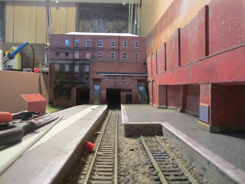
I decided to tunnel out and widen the station through the retaining wall and underneath the rising main line. I can't think of a single prototype situation where this occurs, so its a definite case of Rule 1 applies.
First picture shows the holes cut in the retaining wall.
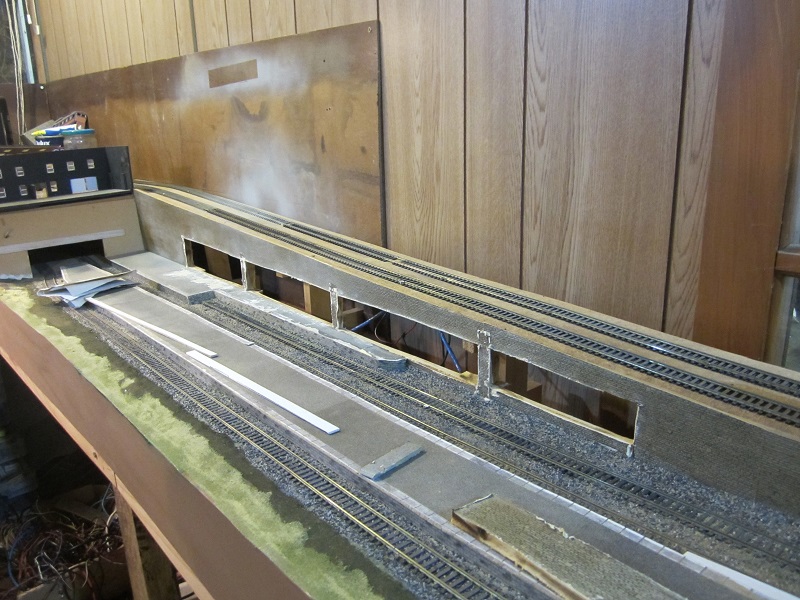
The second picture shows the card base structure for the new platform.
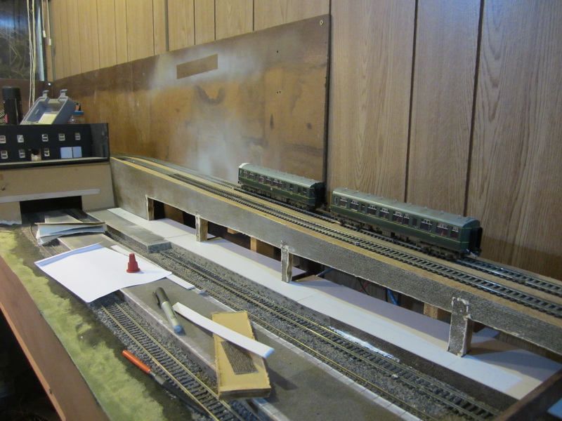
Tomorrow I will start on some walls and canopies… watch this space.
Last edit: by Wizmacnz
Posted
Inactive Member
Anyway.. I've been working slowly on my Lower Bidley Station. The station really is lower because you enter at street level on the far side from the pictures below and descend, by lift or stairs, 4 floors to get to platform level. I started modelling this building about 8 years ago and its been somewhat battered over the many stop, start, remove and put back operations that have taken place through this period.
Still has some way to go and quite a bit of touch up of previous damage to put right, but here are a couple of progress shots.
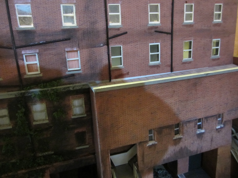
Interior lighting has been installed by sandwiching LED's between two thicknesses of card. I used the square flat LED's that I've use before cut off a roll of LED's. I drilled holes in the ceiling to line up with where the LED is mounted. This way all the wiring and the LED itself is hidden.
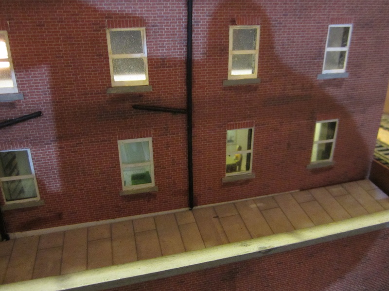
The rooms are internally decorated using a mixture of Scalescenes and my own 3D printed furniture.
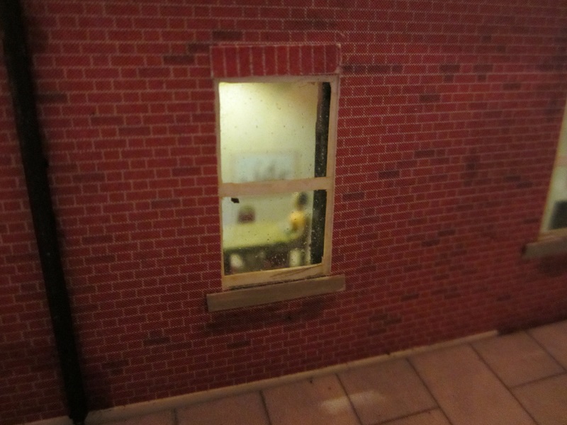
I never remember to clean the windows before taking pictures. When I stated making this all those years ago, I just got some black foam board, stuck some brick paper on it and cut holes in it for the windows. Window frames are white sticky label stuck onto acetate and are somewhat balanced in the openings. Next building will be a bit more sophisticated.
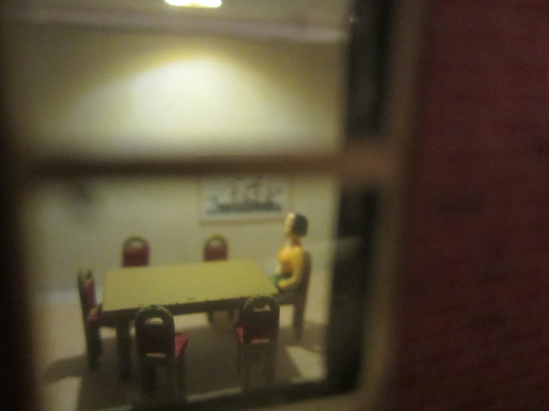
This poor lady is condemned to an eternity in a boring room with ill fitting windows. No one is going to be bringing her dinner anytime soon.
Last edit: by Wizmacnz
Posted
Inactive Member
There will be an overall canopy coming forward as far as the end of the bay. And then a platform canopy continuing on the island platform and a cantilevered canopy running alongside the bay.
The picture below shows the first section of high level overall canopy, balanced in place. I'm waiting to see if some Chinese lights I've bought off fleabay will be capable of being adapted to suit the canopies and if so wiring them in before installing the canopies. I've also got to get those leaning pieces straight and cover everything with signs, adverts dirt and grot while I can still get to it to do it. Platform walls will also be changed to brick.
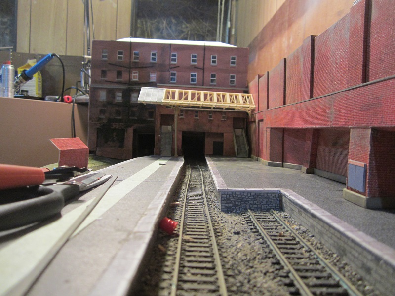
It's amazing the things you notice when you put the camera down at track level. … so that's where the cap from glue went.
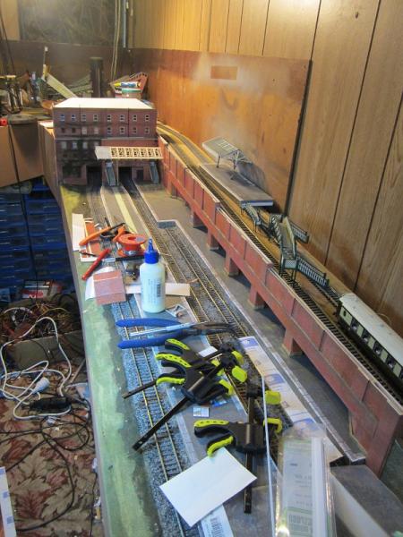
The last picture is an overall view similar to the viewpoint from a couple of posts ago. I remind you all that an untidy workplace is a sign of a creative mind
Posted

Inactive Member
Max
Port Elderley
Port Elderley
Posted

Site staff
Ed
1 guest and 0 members have just viewed this.