NotMutley - take 2
Posted

Full Member
Freelance 00 layout
Hi Dave.Thanks Tony,
I saw the "upside down" cradle on You tube and decided that for the moment at least it would be a diversion from my main game. It does look appealing though - how useful have you found it ?
Dave
I bought the "upside down" cradle mainly for the stands & haven't used the straps that came with it yet.
Tony.
"The only stupid question is the one you don't ask"
Regards.
Tony.
Regards.
Tony.

Posted

Full Member
Software loaded ok but noticed that the CD is just a plain off the shelf CD which will get lost/misplaced so I need to save the exe files down onto a usb and mark the CD with a laundry marker.
The software intefaces with RR&Co so thats a relief but I need to secure the rolling road before I go any further. There are no plugs /sockets on the rolling road so I need to sort out some robust wiring and make it Pearson proof so that I do not end up with it all on the floor!
D
 Last edit: by gdaysydney
Posted
Full Member
This morning I made some changes so that the rolling road and wiring was secure enough to enable me undertake further testing
As a rolling road it works well - very stable so that box is ticked.
The big question was now would it work with RR&Co and I am relieved to say it does although I have only profiled one loco and that was done" on the fly"
I was half expecting the process to be fully automated but its not. At each decoder setting you have to manually stop the loco and enter the speed calculated by Speed cat - this I found aligned very closely to RRCo particularly so once the loco got to a scale speed of 15mph.
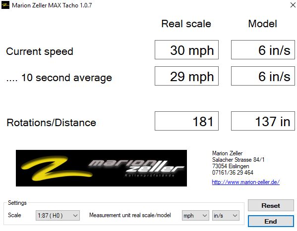
This is a screen shot from Speedcat - it shows the current speed and the ten second average. I waited until the loco was up to speed and the distances were steady and the speeds closely aligned before stopping the running and entering the values in RR&CO
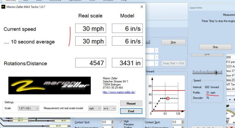
This next photo shows the Speedcat and RR&CO together during the process.
The top left corner shows part of the RR&CO screen where you enter the speed value - I'll take another screen shot when I am profiling the next loco.
This particular loco was programmed to run at a top speed of 30mph
Verdict
I had some initial issues with a conflict over the COM ports but I found that if I started RRCO first Speedcat was happy to load up and find its own ort - so not as fussy as RR&CO.
In terms of my objective it ticks the box - no need for a special long track for speed profiling and as an added bonus profiling takes a lot less time as the run time for each measure is determined by you - I guess it will be trial and error as to the maximum time needed. - One down side is that unlike speed profiling on the track it does need manual intervention but that is a plus form my perspective.
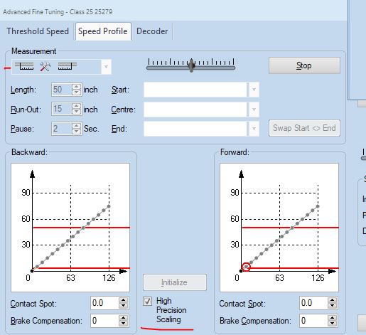
On a tangent issue I noticed that Version 9 has an additional box on the speed profiling window which I have underlined in red. John, have you used this and does it make any difference? ( I ticked it and ran my test profile above)
Now to solve my wagon detection problem. My post has still not appeared in the NCE forum - Ill have to relodge it.
Dave
Posted

Site staff
it is now there Dave
Ron
NCE DCC ; 00 scale UK outline.
NCE DCC ; 00 scale UK outline.
Posted

Full Member
That looks very encouraging although I am a bit surprised that you have to make manual entries.
A few questions
I guess on a rolling road it doesnt matter whether it is HO or OO?
I realise its a test but will you be re profiling after adjusting cv 5 (and 6) to get 30 mph at speed step 28? Otherwise you lose a lot of speed steps.
I guess you still do brake compensation on track?
I hadnt appreciated, until recently, that to get the best stopping accuracy your schedules should reflect the speed and stopping distance used in the brake test. I used to have a standard 18" at 15 mph……now I do horses for courses……I do 4-6-0s at 30 mph 36 " forwards but 10 mph 12" backwards (ie coupling) and have similar speeds and distances in the schedule
My apologies …..I meant to tell you about that box………..yes it needs to be ticked to get the enhanced performance from V9………….I find that reprofiled locos stop more accurately and of course do limited distance moves….magic!
Regards
John
Posted
Full Member
Thanks Sol, I see its my original post - there will be another soonDave wrote "Now to solve my wagon detection problem. My post has still not appeared in the NCE forum - Ill have to relodge it."
it is now there Dave

There were plenty of replies and the answer appears is to reduce the value of the resistor not increase it as I have been doing :sad: I will need to get out my old physics book and brush up on Ohms law
Good to hear from you
regards
Dave
Last edit: by gdaysydney
Posted
Full Member
Hi John,Hi Dave
That looks very encouraging although I am a bit surprised that you have to make manual entries.
A few questions
I guess on a rolling road it doesnt matter whether it is HO or OO?
I realise its a test but will you be re profiling after adjusting cv 5 (and 6) to get 30 mph at speed step 28? Otherwise you lose a lot of speed steps.
I guess you still do brake compensation on track?
I hadnt appreciated, until recently, that to get the best stopping accuracy your schedules should reflect the speed and stopping distance used in the brake test. I used to have a standard 18" at 15 mph……now I do horses for courses……I do 4-6-0s at 30 mph 36 " forwards but 10 mph 12" backwards (ie coupling) and have similar speeds and distances in the schedule
My apologies …..I meant to tell you about that box………..yes it needs to be ticked to get the enhanced performance from V9………….I find that reprofiled locos stop more accurately and of course do limited distance moves….magic!
Regards
John
Early days yet - the loco was one I just grabbed to test and yes it does need to have the decoder reprogrammed,
I haven't got around to adjusting the break compensation but yes I would expect to do that on the track.
Once I get more experienced with the rolling road and speedcat I post more detail - potentially a video showing how it works ( no promises but)
Dave
Posted
Full Member
The guys on the NCE forum were very helpful in pointing out that I was doing the wrong thing by increasing the value of the resistor across the wheelset and so today I commenced testing lower value resistance and values between 3k and 4k appear to do the trick.
I have some surface mounted resistors within that range so I am giving it ago as per the video in an earlier post and this video.
Both videos make it look easy but with my fat fingers and diminshing eyesight its taking me a while to end up with an axle that works :sad:.
The first attempt I glued the resistor - let it dry and then put the electic paint - waited for it to dry and tested the result with a meter and ….. nothing - close inspection ( or as close as I could see) revealed that maybe I had allowed paint across the top of the resistor( which are extremely tiny).
So now I test at each stage. I am using wheelsets with plastic axles to start off with as they should be easier than wheel sets with metal axles and plastic insulation at the wheel. I also have resorted to using wire rather than a toothpick which I found to hold too much paint.
I also took notice of the commentary in the video linked in this post and covered the paint with coloured varnish to protect the paint as it will scratch off and to make idenfication of wagons with resistors straight forward. ( Varnish couresty of "she who must be obeyed" ) Here it is
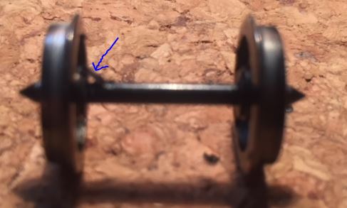
apology for the picture quality - but just to give you an idea of the size of the resistor which is the small lump indicated by the arrow. This wheel set has a plastic axle hence the location of the resistor.

My next attempt is with a metal axle with insulators in each wheel. Again apology for poor photo quality. This time the resistor is mounted diagonally across the insulator. Electric paint added to both wheels to complete the circuit. Varnish yet to applied.
Dave
Posted
Full Member
This was feedback from McKinley Railway who are using TC version 8 -Hi Dave
I am very interested to see how you get on with the Speed Cat interfacing directly with TC particularly if it retains accuracy and saves time

I'm not familar with the "frig factor" in TC and I suspect it is no longer there in Version 9 :roll:
Posted
Full Member
I checked the V9 railroad.ini file. There is no mention of either a zeller or a frig factor but in the section with profiling info there was something about rolling road
Cheers
John
Posted
Full Member
I have now been distracted again by NCE's final solution for signalling- having waited years for their Sig decoders they have finally released what looks like a much better and versatile solution call Light It - stationary decoders about the size of a five cent coin that can be used for a wide range of uses including signalling.
Light It
Now which should I do first ????
- Finish tidying up the train room
- Finish profiling my locos
- Finish fitting resistors to my wagons
- Start on applying ballast to the track
- Finish the scenery on the layout
Posted
Site staff

Ron
NCE DCC ; 00 scale UK outline.
NCE DCC ; 00 scale UK outline.
Posted
Full Member
Posted
Full Member
Thanks Sol,While you are thinking, partake in a glass of red :cheers- it may help to clarify what is done first !!!
I took your advice except that while I was drinking the first glass I just ran trains.
By the time of the second glass the computer was running the trains and by the third glass I tried running trains in conjunction with the computer which didn't work out well as I went through a red light'( well would have done if it had been working!) and caused a derailment. :roll: At that point (pardon the pun) I decided to switch everything off and tidy up in the morning

Posted
Full Member
I mentioned before that these decoders are small - the plus side is that they can be located inside wagons and carriages and full advantage taken of the many lighting effects the decoder can mimic- these include crossing signals, slow fashing, flourescent flicker ( oh the irony !! I have flicker free installed in some of my carriages), Random on/off - 4secs to 4 minutes to name a few.
The downside is that for signals these decoders will be under the board and their small size means there is no room for mounting screws. I will need to give some thought as to how I will set them up as they can be diasy chained. I'm thinking that since double sided sticky tape is problemic over time, I will either use blue tac or mount them on a thin piece of mdf using the power wiring to hold them in place. Any suggestions always welcome
The picture below shows how they come if you elect for the 15 decoder packet - the coin is a 20 cent piece - same size as a 10p coin. The 15 decoders cost me A$140 so less than A$10 per decoder
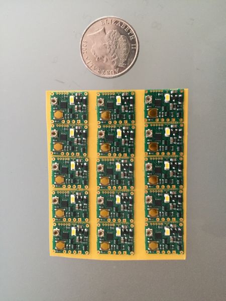
They are powered off the track and the instructions cover programming using the NCE, Digitrax,and Lenz systems. I mention this as I know John uses the Lenz system and is looking for something to do (NOT) :twisted:
Last edit: by gdaysydney
Posted

Inactive Member
[user=606]Sol[/user] wrote:Thanks Sol,While you are thinking, partake in a glass of red :cheers- it may help to clarify what is done first !!!
I took your advice except that while I was drinking the first glass I just ran trains.
By the time of the second glass the computer was running the trains and by the third glass I tried running trains in conjunction with the computer which didn't work out well as I went through a red light'( well would have done if it had been working!) and caused a derailment. :roll: At that point (pardon the pun) I decided to switch everything off and tidy up in the morning
:cheers :cool wink
Max
Port Elderley
Port Elderley
Posted
Full Member
Dont tempt me Dave……….my to do list is growing at a frightening rate……you are absolutely correct I do NOT need any more projects…….another glass of wine is another matter!:cheers
They are powered off the track and the instructions cover programming using the NCE, Digitrax,and Lenz systems. I mention this as I know John uses the Lenz system and is looking for something to do (NOT) :twisted:
Posted
Full Member
There are days when I wish I had just stuck to a simple layout with nothing fancy - such as signals that work !!!
Yep you know where this is going… Some of you may recall the frustration I had a few years ago when I set up my signals via a separate BUS using loconet. Light It was supposed to overcome these frustrations and make it nice and simple to install.
So far my experience has not been 100% positive - the decoder is very flexible - which is more than likely my downfall- too many options!!. It can work off loco functions, accessory functions and as a multi aspect signal. No problem with getting it to work on the first two functions, which I currently don' t need, but can I get it to work my two aspect signal - currently NO :oops:
I have reverted to posting on the NCE group again - hopefully they will come to the rescue. Whilst I am confident that I can get RR&Co to run appropriate macros if I set up each signal as a loco ; it will be a pain in the a**e.
I then looked at the RR&Co forum and found this :
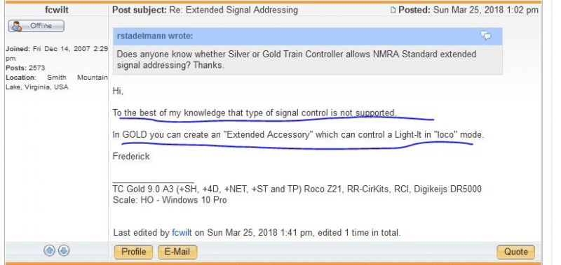
So thats the problem my train software does not handle extended signal addressing !! :twisted: :twisted: :twisted:
Fortunately I am using the gold version so I will have to revert back to the manual on Extended accessories and program by signals as locos ( fortunately my system can handle thousands of diferent loco numbers :cool:
John - do you have any tips on have you Extended accessory programming ?? ;-) ;-)
Oh and one other trap - the aspect signals are made in England and the common wires are negative with the positive wires colour coded for ease of use. The decoder is made in the USA and set up for common being positive. Not a major problem except I had to waste time working out which of the two white wires on the signal was for the red signal, the other being for the green - just something to be aware of.
Last edit: by gdaysydney
Posted
Full Member
I am a bit confused………..if the plan is to use the decoders to power multi aspect signals why would you use the locos to control them………I would have thought TC could operate them like the prototype linked to blocks and turnouts… I suspect I have missed something. Are the signals for cosmetic purposes or will they control the movement of trains?
I have dabbled with extended accessories…….happy to help when I am a little clearer about the overall plan.
Regards
Posted
Full Member
Hi John,Hi Dave
I am a bit confused………..if the plan is to use the decoders to power multi aspect signals why would you use the locos to control them………I would have thought TC could operate them like the prototype linked to blocks and turnouts… I suspect I have missed something. Are the signals for cosmetic purposes or will they control the movement of trains?
I have dabbled with extended accessories…….happy to help when I am a little clearer about the overall plan.
Regards
I thought they would operate as you suggest. Linking the signal to the decoder by a unique address, with logic in TC determining the status of the signal ( using a combination of conditions of turnouts and block occupancy ) and the decoder automatically changing the physical signal.
But it turns out that the NCE decoder uses extended signal addressing which is not supported by TC.
My thought now is to have the signal driven by the logic and hence changing the signal in TC . What I am not sure about is how to set up a "Loco" that is really a signal :???: If I give the signal an address that is a loco I need to work out how to trigger the actual signal as the signal will use functions that would normally be associated with train lights - In this case it would be functions 0 and 2 so a light change would involve two commands function 0 off Function 2 on and visa versa
Any assistance on extended accessories, which I dabbled briefly in a few years ago , or any other thoughts would be greatly appreciated.
As you can see I have been "Railroaded" again
Last edit: by gdaysydney
1 guest and 0 members have just viewed this.