NotMutley - take 2
Posted
#199476
(In Topic #11061)

Full Member
Freelance 00 layout
http://yourmodelrailway.net/view_topic.php?id=9917&forum_id=21 NotMutley RIPNotMutley 2 - the rebuilt commences.
As mentioned in the previous posts in the original NotMutley thread , the new layout will dispense with the two tiers as I was not happy with the steep gradient or access to the fiddle yard which was on the lower level below the station area.
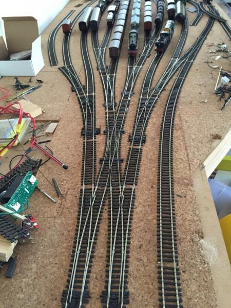
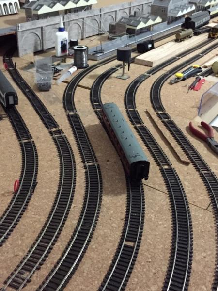
The fiddle yard will remain in the same location but has been modified and includes point work that permits any train to leave the fiddle yard on either the up or down line. In the old configuration the fiddle yard was split into an up and a down section. The use of Y points in conjunction with double slips will give more flexibility.
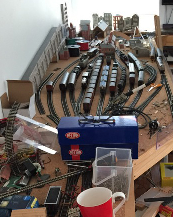
This is a photo taken a few weeks ago - I was going to use it to show the pointwork but someone has left two Heljan boxes on the track
 .
. 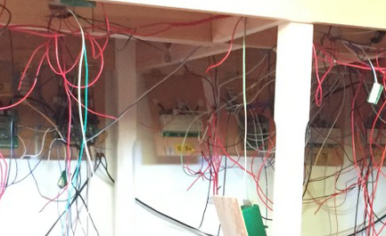
The next shot explains why its taking so long - the wiring for the new track is in place but not connected. The electronics from the old layout has to be removed and recycled, programmed etc….
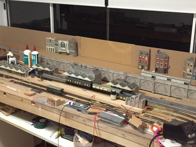
Most of my attention has gone on the window side of the layout where I have extended the width to allow for more room for what will be the station area. This picture shows the extra width ( old layout was to the cork tile).
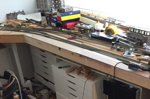
This weekend I spent a bit of time working out how to make the best use of this area and how to stop the strong Aussie sunlight from fading anything that sits near a window..
This is my solution - a removal MDF backboard that sits on the window ledge. It is kept in place at either ends by overlapping mdf and a removal cover that hides a double track that bypasses the station.
This is the view from the other direction - the sun blinds can be drawn down to the backboard to allow some light to enter the room.
Well that's about it - tons of work to do but at least I now feel that I have a workable plan and I finally feel motivated..
 Last edit: by gdaysydney

Posted

Banned
Cheers, Gary.
Posted

Full Member
It's good to see someone with a plan and you seem to have a great starting point with all that work and experience under your belt. Good luck with the rewiring and electronics and I'm pleased to see some brown and cream on your layout!
All the best,
Bill :)
At 6'4'', Bill is a tall chap, then again, when horizontal he is rather long and people often used to trip over him! . . . and so a nickname was born :)
Posted

Inactive Member
Early days but the potential is there for something really good. The Aussie sun is a killer and you`re right to get that sorted out. Your under board wiring reminds me of mine. I`ve just lifted my main board this afternoon to do some work under there and it needs a good tidy up before anything constructive can happen.
So good luck with it all and I look forward to the new version of your layout.
:cheers Gormo
"Anyone who claims to have never made a mistake, never made anything!!"
https://sites.google.com/site/greatchesterfordmodelrailway/home
https://sites.google.com/site/greatchesterfordmodelrailway/home
Posted
Full Member
I actually enjoy the electrical side of the hobby - its just that in this instance I have been lazy and not disassembled the old wiring before starting the new. I have one area of the layout already correctly wired up and working by computer control but there is a lot more to do. Additionally I am running two DCC buses in tandem so that the computer can control signalling ( The NCE system can't handle signals yet although they have been promising signal decoders for many years)
Posted
Full Member
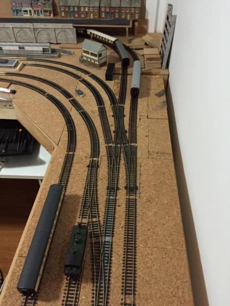
It uses Y points and a double slip to allow access to both the up and down tracks in the fiddle yard.
Posted
Banned
Cheers, Gary.
Posted
Full Member
Hi Gary,Impressive piece of track work. :thumbs Will the line on the far right besides the throat, become a run-around ??
Cheers, Gary.
yes that is the plan - although with me that could change :oops:
Posted

Full Member
Have you met my friend Ron Solly Dave ? ………….[user=878]Gary[/user] wrote:Hi Gary,Impressive piece of track work. :thumbs Will the line on the far right besides the throat, become a run-around ??
Cheers, Gary.
yes that is the plan - although with me that could change :oops:

'Petermac
Posted

Site staff
Do you mean me - doing changes ?? :cool wink[user=540]gdaysydney[/user] wrote:Have you met my friend Ron Solly Dave ? ………….[user=878]Gary[/user] wrote:Hi Gary,Impressive piece of track work. :thumbs Will the line on the far right besides the throat, become a run-around ??
Cheers, Gary.
yes that is the plan - although with me that could change :oops:
Ron
NCE DCC ; 00 scale UK outline.
NCE DCC ; 00 scale UK outline.
Posted
Full Member
yes I have - and yes he taught me everything I know especially how to change me mind[user=540]gdaysydney[/user] wrote:Have you met my friend Ron Solly Dave ? ………….[user=878]Gary[/user] wrote:Hi Gary,Impressive piece of track work. :thumbs Will the line on the far right besides the throat, become a run-around ??
Cheers, Gary.
yes that is the plan - although with me that could change :oops:
Posted
Full Member
 thumbsthumbs
'Petermac
Posted

Full Member
How about "NetherMutley"
Nice start, what system are you using for your second data bus ?
Paul
Posted
Full Member
Hi Paul , I am using RR-CirKit's Locobuffer USB. A small box with one end plugging into the compter with a USB and the other end attaching to a Bus.Hi Dave
How about "NetherMutley"
Nice start, what system are you using for your second data bus ?
Paul
RR-CirKits, Inc. Home Page
Last edit: by gdaysydney
Posted
Full Member
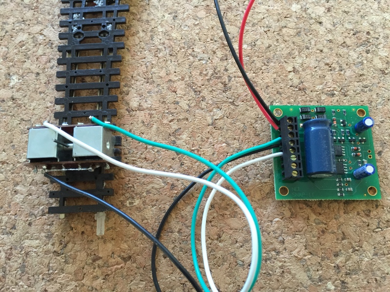
My main Command controller is NCE so the easiest and quickest way is to use NCE's "snap it " decoder in conjunction with a Peco turnout motor.
The picture below was taken to show how simple it is -
The "snap it" does not require soldering as it has screws for the connection of the wires - three from the Peco Motor ( combined wire from the common side) and two wires that attach to the BUS.
If required the "snap it' can control two points at the same time by the addition of an additional capacitor - again no soldering required as it just screws in.
The decoder is programmed using the controller and is easily mounted under the layout near the points so no lengthy wiring required.
adding additional capacitor to control two points simultaneously is simple as adding another capacitor:
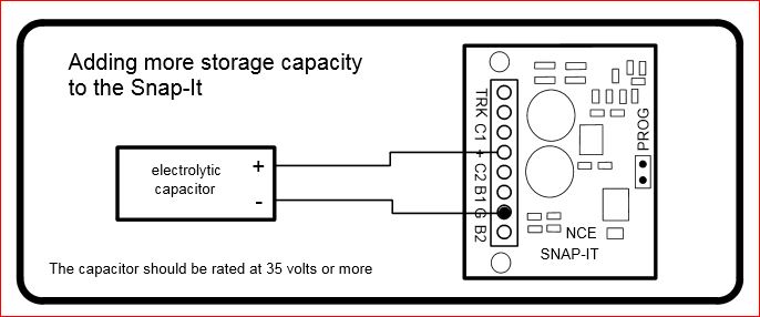
Last edit: by gdaysydney
Posted
Full Member

The time was spent track laying and wiring the points for computer control this time at the south eastern end of the room.
Since I am installing a double crossovers I prefer to use Tortoise point motors as they are not as savage on the point-work.
They are a little trickier to install especially if you do not have a volunteer handy to hold them in place under the layout while you get the alignment right.
To solve this problem I attach double sided tape to the top of the Tortoise so that it will stay in place until I can secure it with screws. I also replace the wire that is supplied with thicker piano wire. The photo below shows one ready to be mounted.

I use a Lenz decoder for these "slow motion" motors as the decoder for the "snap it" is not suitable (NCE do make a suitable decoder but I have not tried it)
To handle The Tortoise motors the Lenz LS150 ( which can control up to 6 motors) requires diodes to ensure the points work correctly - instructions come with each unit but it is a bit of a pain - fortunately diodes are very very cheap.
The photo below shows part of my set up - the orange and yellow wires are to a separate power supply and the black and red leads go to the track power supply, which in DCC speak its called the BUS.

A bit more time consuming and more expensive than the " snap it " approach but saves delicate point-work such as double slips from being pulverised.
The other point to mention is that the Lenz decoder works fine with the NCE digital system
Posted
Full Member
This enables me to use the computer to control everything - its a funny thing but after approx 6 months with the layout not being operational its good to have the computer software set up albeit only as a control panel.
Posted
Guest user
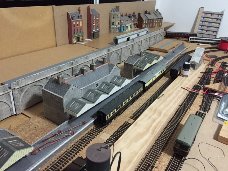
I also like your retaining walls. :thumbs
Cheers
Toto
Posted
Full Member
The retaining walls are Scalescene, which I have found to be great value for money especially if you need to replicate many times. They have been recycled from the old layout where they made up a wall of some 15 feet. As with all the scenery they are in situ just to give me a starting point for the final layout . They currently hide the loop that bypasses the station area and I am pondering whether to have a road on top or another railway line with hidden ends that would run railcars back and forth - something that would be easy to do under computer control but may make access a tad problematic.

Posted
Guest user
I'll be doing something similar to hide a gradient climb up to an upper level terminus station on the R & GLR. A mixture of retaining walls and landscape.
I'll look forward to see how you go with yours.
Cheers
Toto
1 guest and 0 members have just viewed this.