Newton Regis, it'll never be finished, hopefully!
Posted

Full Member
A GWR journey through the 1920s and 30s
Quick tipIt’s amazing how necessary track cleaning becomes in so short a time, even when a layout is located in a ‘clean’ environment. Today’s testing was necessary on reinstalling trackwork to the livestock siding and my 64xx pannier hesitated at crawling speed over several sections, so out came a trusty wooden lolly stick to burnish the tops of the track and all was well. The good news therefore, particularly for sweet toothed modellers, is that you have an absolutely valid need to buy multi packs of mini choc-ices on sticks, so don’t delay!
FYI: after months of extensive testing, Magnums seem to be most effective for this modeller, so they have my objective recommendation, as a satisfied user of the product.
Enjoy,
Bill
 Last edit: by Longchap
At 6'4'', Bill is a tall chap, then again, when horizontal he is rather long and people often used to trip over him! . . . and so a nickname was born :)

Posted

Full Member
Do you put anything on tge stick before burnishing or simply rub with the wood ? Hithertom I've used IPA for the major cleaning with either hardboard or a Gaugemaster track rubber for intermediatecleaning. The Gaugemaster rubber seems far kess abrasive than the Peco version but I'm trying to move away from rubbers altogether. Lolly stick would offer a very tasty alternative.
'Petermac
Posted
Posted
Full Member
Liquid is not required or desired for burnishing, although for a deeper clean, such as may be necessary with heavily oxidised track, a rub down with IPA on a cotton bud would be appropriate, followed with the Magnum stick when dry.
I use a flat side of the lolly stick to burnish (rub) the surfaces of the rails, although I did find a small stray solder spot on the rail which had oxidised, so the edge of the stick was sufficient to dislodge the spot prior to burnishing.
I’ve not yet had a need to introduce abrasives and don’t intend to start, despite having a new Peco track rubber looking for alternative employment. If abrasives became necessary, I’d try some 1000 or even 2000 grade wet and dry paper, glued to a lolly stick, used dry with consistent light pressure for a few seconds. Of course, I currently have only a small track section of the layout laid, so cleaning is not a burden. When the time comes, I’ll adapt the cleaning methodology to suit.
Flavour choice fortunately does not compromise the effectiveness of the cleaning efficiency and the selection between classic milk and white choc is dependent on mood, although the bride is particularly partial the nutty choc covering. The debate could easily be extended to eating methodology and oral pre-cleaning of the stick, but such technical discussion can wait until a sillier day!
Best,
Bill
Last edit: by Longchap
At 6'4'', Bill is a tall chap, then again, when horizontal he is rather long and people often used to trip over him! . . . and so a nickname was born :)
Posted
Full Member
B

Last edit: by Longchap
At 6'4'', Bill is a tall chap, then again, when horizontal he is rather long and people often used to trip over him! . . . and so a nickname was born :)
Posted
Full Member
Not still using 'rubbers' at your age Peter!
'Petermac
Posted
Full Member
Apparently so Derek, and magnum sized to boot!
B
Oh how well you know me Bill …………………….. :cheers
'Petermac
Posted
Full Member
Part 2, In which we do some planning, then actually make a start
Part I, Droppers, was aired in post 248 and now we move forward with other underboard wanderings, which will be installed in a reasonably logical order, although I’ve already digressed by painting the undersides of baseboards after installing the droppers! No matter, just a case of memory lapse producing a whiter shade of pale red and black droppers. At least I remembered to paint them before getting any further. Note to self: don’t give the game away by advance listing your logical order for electrical gizmotry and set yourself up for deserved slapped wrists through divergence!
So rather than set out an alleged ideal work plan, I’ll next be installing the following, in no particular order:
- · Track power bus
- · Track power supply, control gear and circuit breaker
- · Accessories bus – for point motors, uncoupling electro-magnets, signals and lighting
- · Point motors, wiring and control panel
- · Electro-magnet(s) for automatic uncoupling
- · Signal, yes that’s currently in the singular as far as operating units are concerned
- · Anything else I’ve forgotten about, including labelling all the gizmatry
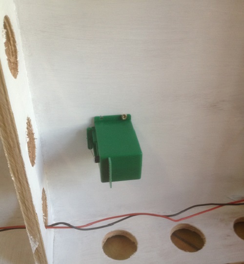
. . . point motors. This is actually quite logical, as I need to know where all the motors are located before running cabling across the baseboard, in order to avoid conflict and unnecessary relocations. When the Tortoise motors have been tested as working satisfactorily, I’ll add the other two screws and drive them firmly home. I was pleased how quickly the first motor was fixed using the plastic location template, which is positioned under the baseboard hole for the actuation wire, with the template showing you exactly where to mark the placement of the four fixing screws. The remaining motors should be even quicker.
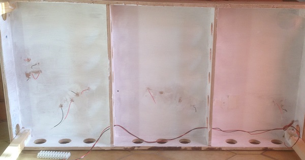
You’ll see that I’d previously made a start a while back with loosely twisting red and black power bus cable together and posing it along the back of the main baseboard to decide how I was going to fix it in place, before I got side tracked with some buildings. The cable bus will now be relocated along the front of the boards, to enable quick access for trouble shooting without having to bodily get underneath the layout. Fortunately, I can easily sit under the layout, although the installation process is being carried out with the boards propped on their sides.
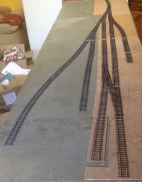
Any finally, for now, a reminder of the track plan:
I’ll be back to the boards tomorrow to complete fixing and testing the point motors and using the same logic of locating all the fixed equipment before wiring, will give thought to the number and location of magnets and marking the signal location.
Take care,
Bill
Last edit: by Longchap
At 6'4'', Bill is a tall chap, then again, when horizontal he is rather long and people often used to trip over him! . . . and so a nickname was born :)
Posted
Full Member
A lazy Sunday start, which often seems appropriate on this traditional day of rest, saw me back with a 9v battery and a pair of miniature jump cables by mid-day to fix the rest of the point motors and test them insitu for actuation of the points. First task was to sensibly bench test all six motors and following the satisfying slow whir of the machines, I fixed the second of the two to the first baseboard in just a couple of minutes, having first bent up the spring steel actuation arm to the required profile and secured it to the motor. Both motors were now attached to the plywood with actuation levers pushed up into view above the baseboard. Now things get more entertaining.
Although this is not my first layout, it is the first to use point motors and finescale points, so whereas I was confident in accurately fixing the motors to the baseboard, I had no experience of fitting the actuating arms through the fulcrum, baseboard and tiny hole in the tie bar. I thought it had been surprisingly easy to place the motors into position while pushing the lever up through the baseboard, but both were in fact uselessly resting to the sides of the tie bars.
The thin spring steel pin requires dexterity of fingers, combined with coordination of excellent eyesight to achieve success. This was no two minute process and as I climbed the slippery slope of this particular learning curve, I realised that (1), I needed to establish an easily repeatable technique and (2), that YouTube videos leave out all the tricky bits!
The installation of the first point took an embarrassingly long time to satisfactorily complete and whilst my technique progresses, it needs further refinement. My hand to eye coordination is as good as ever, although early diminishing winter daylight means I need to start these tasks in the mornings.
The actuation lever was removed from the motor and pushed through the board from the motor side (it has a right angle bend to fix to the motor, so unfortunately cannot be threaded though the tie bar from the easy rail side) and after many attempts, it finally passed through the tie bar and secured at rail level with a sliver of tape attached to stop it falling out again while I persuaded the other end into another tiny hole on the point motor, then secured it with a fixing screw.
Just a little tweak of the fulcrum height saw a most satisfying switch of the first point and the second will be continued next morning.
Sorry for this blow by blow tale of slow progress, but rest assured that the other motor should soon be completed, followed by those to the other baseboard a few days later (probably?!!)
Best,
Bill
Last edit: by Longchap
At 6'4'', Bill is a tall chap, then again, when horizontal he is rather long and people often used to trip over him! . . . and so a nickname was born :)
Posted
Full Member
They can be the very devil to fit - easy of course, if you have 2 heads and 3 arms each 7ft long but I understand there are more than a few of us who are not thus equipped …………….
I think you said you can sit under your boards - mine are in between - just too high to lie under but not quite high enough for sitting. However, I found the easiest way to fit these motors was to position an LED light (I have a sort of small reading light with a flexible swan neck) above the requisite point with the light shining through the hole in the tie bar then lie/sit under the board and poke the operating wire up through the illuminated hole. With the operating wire left long enough, one can "sight" along it at an angle to find the hole before squaring the motor up in position and fixing. Finally, cut off the surplus operating wire with a decent pair of side cutters - it's hard-drawn wire so takes a bit of nipping (I use piano wire for the operating wire rather than the very thin stuff supplied with the Tortoise motors)
'Petermac
Posted

Full Member
I was going to ask you about the length and type of wire you are using but I see Peter has beaten me to it. I also used piano wire for my installation. I found the wire provided by Tortoise didnt always have enough oomph to throw the tie bar if the spring was left in the turnout…….something I tried to do where possible. I cut my wires a good 1" over length and only trimmed them to size with pincer type wire cutters once the tortoise was finally secured in place.
Forgive the dumb question but your testing routine does include checking for correct frog polarity switching?
Second question…….can you remind me what coupling system you are using?
Best wishes
Posted
Full Member
Regarding questions, actual and implied:
- I removed all the point springs and am using the standard supplied operating rods, the ends of which will be snipped off with my indestructible Knipex side cutters when all motors are installed and fully tested, including polarity (thanks again John). I do have a supply of piano wire (now probably rusty) in a box, previously used for under baseboard point rodding on my first 1980s layout.
- Couplings are the DG type with delayed uncoupling function, manufactured by MSE and supplied by Wizard Models. I first noticed these on Nick Wood’s “Much Murkle†thread, then later saw them in action and after talking with Nick, decided that these should answer my requirements well enough. Activation will be via electro magnets placed in the goods yard, livestock bay and at the far end of the platform. Looking at the track plan again, I think operations may dictate a fourth, but this can only be determined through testing. I carefully checked for free space under the baseboards for point motors before setting out the track plan, but have not as thoroughly done so for electro-magnets, so some adjustments to cross braces may, or possibly may not be necessary.
Best,
Bill
Last edit: by Longchap
At 6'4'', Bill is a tall chap, then again, when horizontal he is rather long and people often used to trip over him! . . . and so a nickname was born :)
Posted
Full Member
Glad you had a more successful morning! You may want to fo some tests to ensure that the issued wire is always adequate. Its so long ago I cant remember all the reasons for shifting to piano wire but I do remember it was near standard practice by modellers who I held in high regard.
Another test you might want to carry out would be to buy a kadee surface magnet and glue it lightly with pva and use it temporarily to establish the exact location for the permanent electro magnets.
As you know I only have surface magnets but you would be amazed at how often I had to shift them around to establish the location that would work for all locos/ trains that would be uncoupling.
Best
Posted
Full Member
Posted
Full Member
I’ll do some more in the morning and before long, it will be done 😊
There’s some interesting conversations on the web from both sides of the pond concerning opinion on best wire thickness to use with Tortoise motors. There seems equal numbers of chaps favouring standard and heavier wire, although modelling factors are not always clear. Advice from manufacture Circuitron advises use of their standard 0.025†diameter wire with baseboard construction not exceeding 1†(25mm) thick and suggest a heavier wire for 7mm scale railways. My understanding of this, is that longer throws of the wire passing through baseboards greater than 1†thick, risk the wire deflecting and potentially not throwing the point blades. Additionally, the presence of tie bar springs present further risk of deflection, hence the need for a stiffer wire lever to move the tie bar.
As I model in 4mm scale, with 9mm thick plywood and 2mm cork track bed to running lines, I appear to be well within the 25mm safety zone, so the provided wire should work fine.
I like your suggestion of using lightly glued Kadee magnets to determine optimum permanent locations John. I have some Pratt & Winkle surface mount magnets and can use these in testing. I may even unpack some old P&W fitted stock to see if they still work.
A question to ponder: may there be some wisdom using a thin layer of, say latex rubber, between the Tortoise and baseboard in an effort to reduce noise drum effect from the plywood sound box structure? Has anyone tried this and with what result please? 08/12/21 Edit: my light bulb moment tells me that if you screw the point motor to the baseboard, then no amount of rubber or cork will stop sound transmission through the screws! Stupid boy Pike!
Best,
Bill
Last edit: by Longchap
At 6'4'', Bill is a tall chap, then again, when horizontal he is rather long and people often used to trip over him! . . . and so a nickname was born :)
Posted
Full Member
Well done. I dislike installing point motors under the board. It always takes longer than I think it should!
Thanks Chris, this was the start of a new learning curve for me, so I'm banking on the process becoming shorter with more practise. Fortunately, there's only four more to go!
Have you started your new job yet? I hope it goes really well for you.
Best,
Bill
Last edit: by Longchap
At 6'4'', Bill is a tall chap, then again, when horizontal he is rather long and people often used to trip over him! . . . and so a nickname was born :)
Posted
Full Member
I have started the new job, I’m a month in. All going well, I can get back to thinking about the railway now!
Posted
Full Member
Another pandemic year almost past and little sign of being able to roam carefree for a time yet to come, so please stay safe and warm this Christmas and God bless us all and those we love.
Warmest wishes to every single member of YMRC, no matter what colour your rolling stock may be, your age, sex, race or inside leg measurement.
Merry Christmas and as healthy and happy and harmonious future to you as may be possible!
Bill
Right, just time to go and make the bride her Christmas card.
Last edit: by Longchap
At 6'4'', Bill is a tall chap, then again, when horizontal he is rather long and people often used to trip over him! . . . and so a nickname was born :)
Posted
Full Member
Here's wishing you and yours all the very best for Christmas and the New Year. Surely, things must improve in '22….. :roll:
'Petermac
Posted
Full Member
I share your hopes for a better 2022, but I'm not confident for my planned UK trip at the end of next month, but await with my glass almost half full, comdab.
Very best to you and Liz,
Bill
At 6'4'', Bill is a tall chap, then again, when horizontal he is rather long and people often used to trip over him! . . . and so a nickname was born :)
1 guest and 0 members have just viewed this.