N Gauge - Newcastle Emlyn****
Posted

Full Member
Marty - have you seen this pic?
A reliable source seems to think it was taken on the Newcastle Emlyn line, but not sure which station.
Just a bit of nostalgia…
(I have ownership of the original photo, BTW)
Shaun.
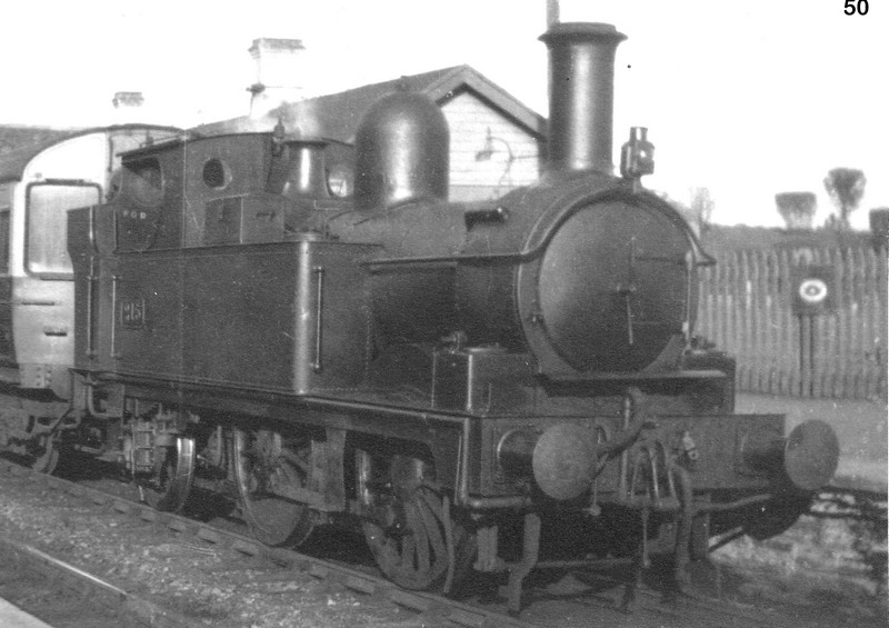
Did a bit of research, if it is on the Newcastle Emlyn branch then it's at Pencader because it was the only timber built railway station on the line. The building chimney arrangement matches and the fence is in the right place.
The loco is 517 class 215 and No's 219 and 222 were recorded on the branch in 1922, so it's feasible.
And auto coaches appear to have been used in Wales too.
The reference books that I use don't show auto coaches in use on the branch, indeed there are some great photos of ex Slip coach W7999 in use from 1948 until close of passenger services in 1952.
Without researching specific engine and auto coach allocations I would say that it is plausible that the photo is of a train about to run on the NE branch.
Which delights me, I had resigned myself to running the auto coaches that I purchased on my layout as unprototypical… Now it seems that they were used…. Brilliant. Many thanks Shaun, terrific work.
Cheers
Marty

Posted

Full Member
Anything you need from West wales just let me know…
Best,
Shaun.
Posted
Full Member
Time for another update, the pace of work and life has accelerated again and while modelling progresses in bits and pieces as a form of relaxation, finding the brain power to put developments down in words and to wrestle with the software is often beyond me.
Thanks all for the interest and comments, they are most welcome and appreciated.
Ed, a concerted effort on those windows over a day pushed that particular building forward far quicker than previous ones…. And maybe the 2mm nocturnal builders did help too.
Thanks Boilermaker for the heads-up about the Newcastle Emlyn disused stations update, they've done a great job, just one photo caption that needs a little tweaking. I plan to send them an email when I get aroundtuit!
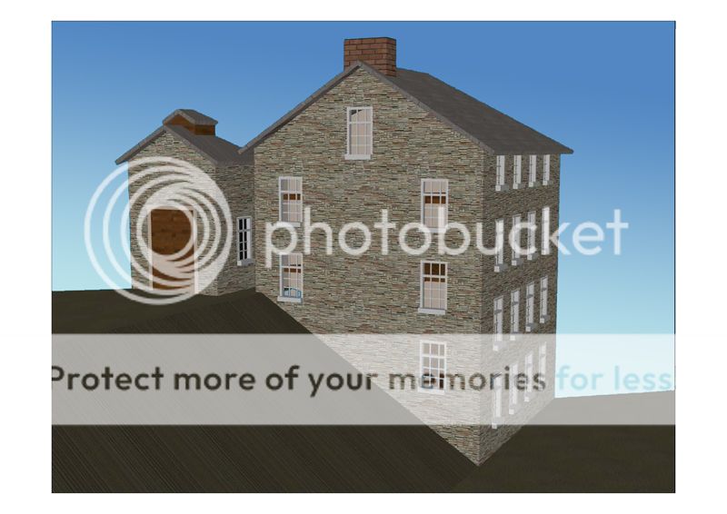
The next building in the Mill Complex is only vaguely seen behind the recently completed one in one photo that I have. I've decided that it was a storehouse of some kind with big doors and a roof ventilator.
Modelled up in CAD it looks like this…
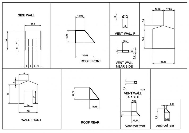
…and broken down into wall elevations and roof plans looks like this…
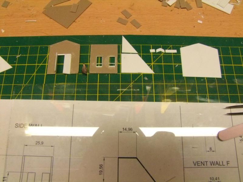
Being small and with not too many windows (thank goodness) it didn't take long to cut out the constituent parts, here display beside a reclining Colonel (Retired) Frobisher from the railway inspectorate…
A top view of the glued together building shows again the diagonal half-relief that is needed to get the Mill complex into this part of the layout.
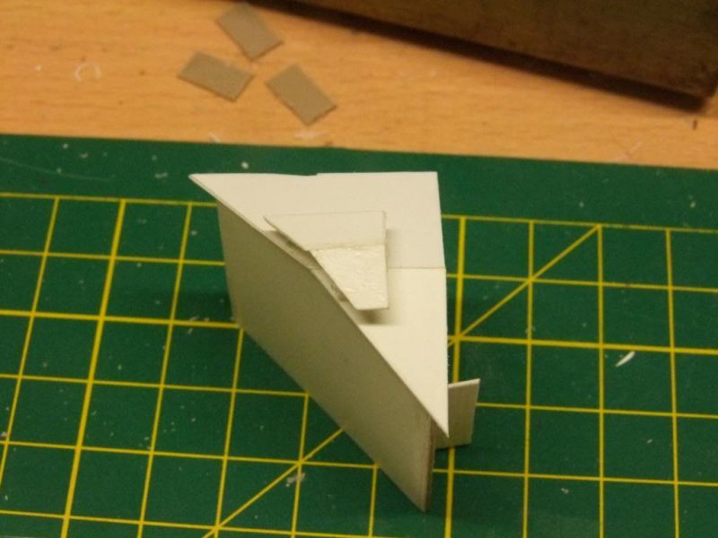
With doors, window frames, glazing, barge boards and gutters the only thing that was an absolute c@*k up was the corner join of the walls. The camera is of course in full macro mode and 2 inches away from the model and with a bit of luck a bit of fettling and some paint will disguise it. Must do better.
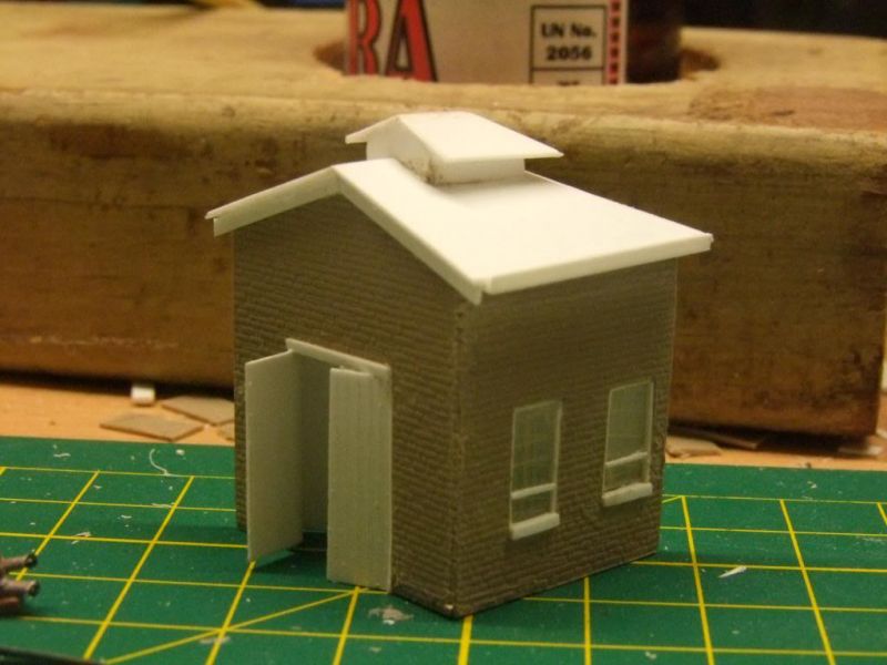
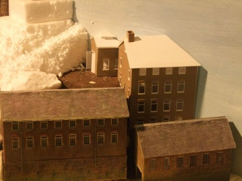
…and here it's is next to its bigger brother on the layout.
Cheers
Marty
Posted

Full Member
What CAD software are you using by the way ? I've recently started using 'Sketchup 8' which seems to be adequate for my purposes.
Regards,
Trevor
Trevor
Posted

Banned
Now, if I send you some pics, could you… ;-);-)
Cheers, Gary.
Posted
Full Member
Nice little building that fits in well with the overall development.
What CAD software are you using by the way ? I've recently started using 'Sketchup 8'Â which seems to be adequate for my purposes.
Hi Trevor,
I'm using AutoCAD ver 13 as its the primary drafting software hat I use in the office. Creating these buildings and the various plans has been a useful training and development exercise.
I've used sketchup and quite like it, although I am yet to work out how to generate the plans from it.
Cheers
Martin
Posted
Full Member
That's some fine modelling Marty, and I don't mean fine as in small ! Those drawing (cad and plan) are fantastic. IÂ assume it would take out all the guess work for cutting, fitting etc.
Now, if I send you some pics, could you… ;-);-)
Cheers, Gary.
Yes Gary, it does, especially with the 30 deg half relief slice across the back of the model.
Send me the pics… And I'll send you a quote :lol:
Cheers
Marty
Posted

Site staff
He, Marty, has to pay for his recent trip to Melbourne
Send me the pics… And I'll send you a quote :lol:
Cheers
Marty

Ron
NCE DCC ; 00 scale UK outline.
NCE DCC ; 00 scale UK outline.
Posted
Full Member
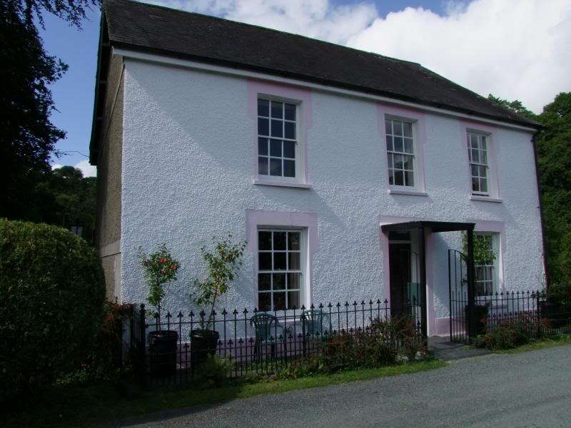
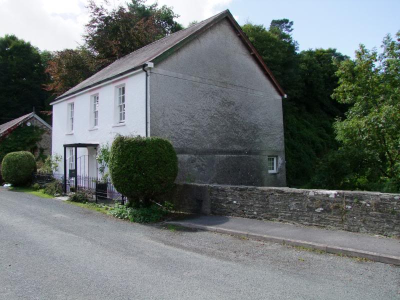
The next building in the Mill group is a favorite of mine and I call it the Mill House for want of better knowledge. Maybe the mill managers family lived there. It's perched up high on the hillside, access to the front door from the approach to the bridge and it features prominently above the valley.
It still exists and was for sale a couple of years ago and I looked very hard at it… but the £500 000+ asking price was out of reach
 , not too mention the relocation from Oz to Wales!!!
Anyway, enough rambling… in CAD it looks sort of like this at the top of the hill….
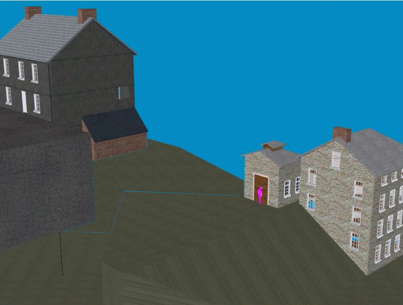
and the plans look like this…..
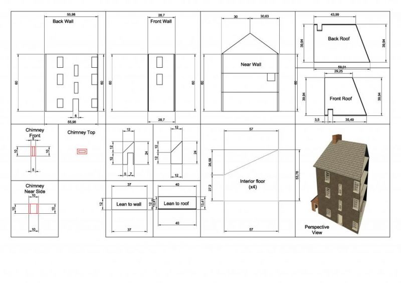
this build I'm going to do as a blow by blow of how I did this particular house as it may be of use to somebody, especially the window frames!! :shock:
Posted
Full Member
I can get them at the weekend if you do.
Shaun.
Posted
Full Member
I've got some front photos from 2010 and a rear snap from the real estate brochure so I think I'll be OK.
Thanks so much for offering though.
You wouldn't have any photos of the Henllan goods shed and/or station building would you? I've got a couple from the GWR journal but I could do with more.
The Mill House Front
The Mill House River Side
cheers
Marty
Posted

Full Member
Always try to look on the bright side of life!
Barney
Barney
Posted
Full Member
Posted
Full Member
Regards,
Trevor
Trevor
Posted
Banned
But if it was a trip to Melbourne for an 'N Gauge Modellers Meeting', that would have been just a 'small' trip…! ;-);-)[user=19]Marty[/user] wrote:He, Marty, has to pay for his recent trip to Melbourne
Send me the pics… And I'll send you a quote :lol:
Cheers
Marty
Cheers, Gary.
Posted

Full Member
Cheers,John.B.:thumbs
Posted
Full Member
It actually went for £320,000! (according to Zoopla)It still exists and was for sale a couple of years ago and I looked very hard at it… but the £500 000+ asking price was out of reach
I'll see what I can find regarding Henllan buildings.
ATB
Shaun.
Posted
Inactive Member
I have just spent a bit of time catching up and was impressed with the mill buildings you have made, you are quite justified in feeling proud of what you've achieved.
I am looking forward to seeing the house progressing now.
Jim
My layout thread http://yourmodelrailway.net/view_topic.php?id=10930&forum_id=21
Buildings for Hemyock http://yourmodelrailway.net/view_topic.php?id=10931&forum_id=14
Buildings for Hemyock http://yourmodelrailway.net/view_topic.php?id=10931&forum_id=14
Posted
Full Member
Thank you, I'll do my best to make it interesting.
I have been lucky enough to learn from some wonderful craftsmen on this forum, Bob, Perry, Jeff, Wayne, Doug to name a few, and the learning process is ongoing.
This Mill House build is my attempt at adopting the different techniques seen over the years. It's not right, it's not wrong, it's just my way of doing things until I decide to do it a different way.
Hopefully this will help someone, or better still, inspire them to have a go themselves..
Using the sections printed out from the 3D CAD model as a guide makes measuring and setting out a lot easier. Not everybody drives a CAD station for a living and there is nothing wrong with sketching out a plan with a sharp pencil on a bit of paper.
The print out is under a piece of glass that came out of an old picture frame that had fallen apart.
This build is going to be constructed from plasticard, a 1mm base sheet laminated to 0.4mm face sheet. It should probably be a triple laminate to prevent warping, hopefully the smaller scale will cope with just two. Internal floors can always be added as bracing if needed.
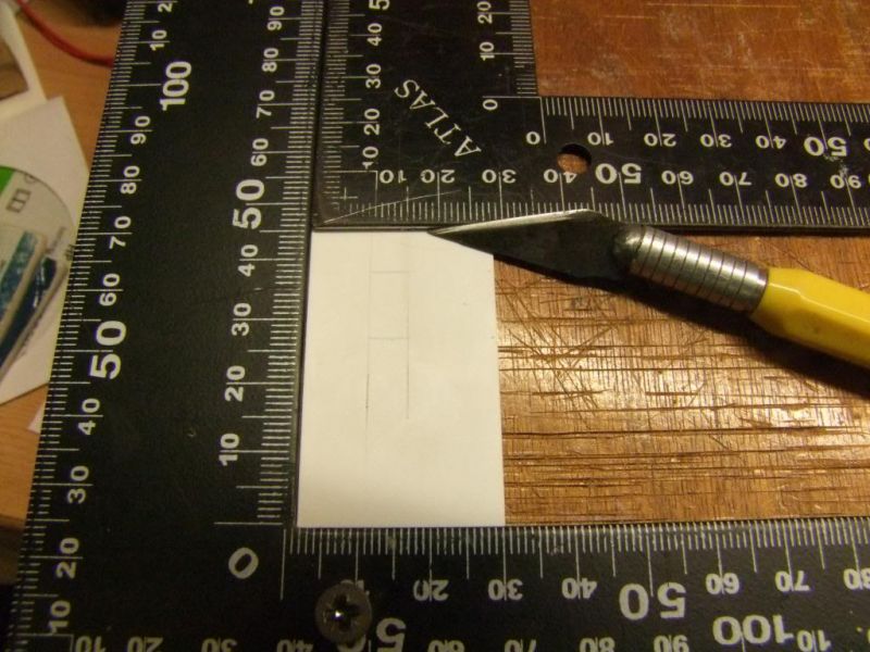
A sharp craft knife is a must, this one is a favourite, using the back of the blade is often a better way of cutting through thicker sheets as it planes out a thin ribbon of plastic, leaving space for the blade to go deeper for the next cut.
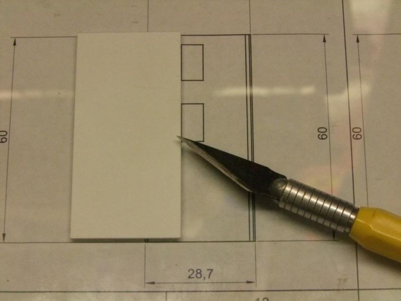
Some sort of device to assist with achieving a square cut is also useful. These are two squares, one fixed to a bit of timber, the other free to slide as required. Not very high tech but it works for me. A chopper or guillotine is on the list… The point of the craft blade is used to mark out a sharp line on the surface of the plasticard, the squares are going to be windows.
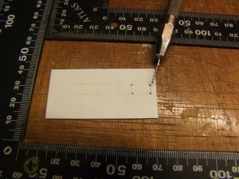
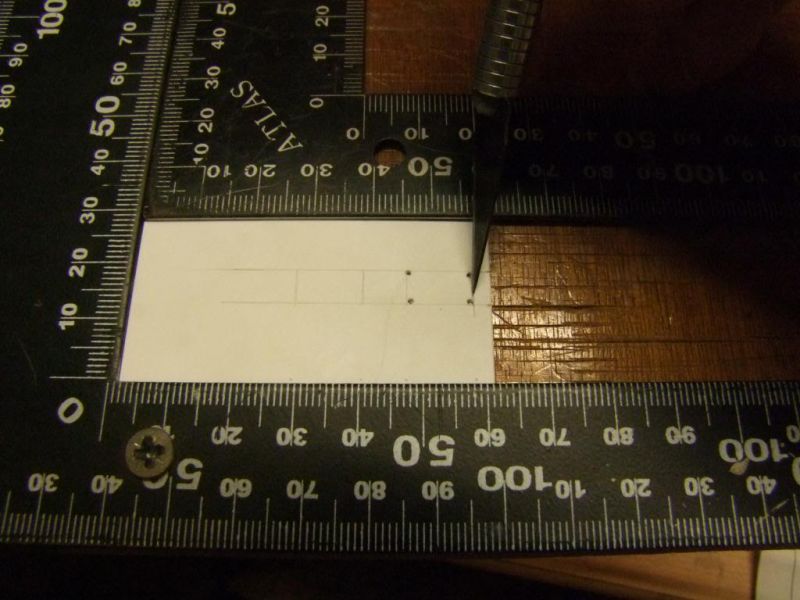
Getting windows cut out and square is always tricky, care is needed, especially in 2mm scale, drilling out the corners helps the craft blade start and stop consistently. You know when you have come to the end of the cut because the blade drops into the hole with a satisfying lclunk.
1mm base on the left and 0.4mm face sheet on the right and a selection of files used to get th windows as square as possible.
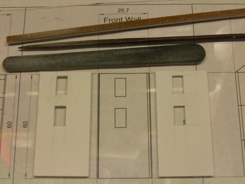
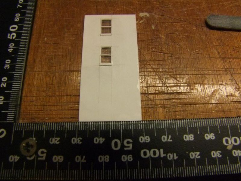
And the sheets glued together with window frames and glazing. This is the bridge side or front of the house, because of the half relief nature of the buildings I don't need the front door. Which is a pity as it is sunken and would have been fun to build.
More soon…. I hope
Cheers
Marty
Posted
Full Member
Looking forward to more.
Shaun.
(For those who don't have CAD, Photoshop will do more or less the same, with a bit of practice)
1 guest and 0 members have just viewed this.